
Roll forming apparatus and system

Inactive Publication Date: 2006-09-26
GENERAL MILLS INC
View PDF8 Cites 1 Cited by
  • Summary
  • Abstract
  • Description
  • Claims
  • Application Information

AI Technical Summary

Benefits of technology

[0005]In order to minimize health risks and production costs, while increasing productivity, it is desirable that the outwardly directing force of each of the guide blades be adjustable to limit the amount of damage to the inner surface of the baking pans. Moreover, it is also desirable to configure guide blades that are easier and faster to clean.
[0006]The roll forming apparatus, according to the various embodiments of the invention includes a shaft member for supporting a head member above a baking container or baking pan containing a unit of dough. The head member includes arms with corresponding guide blades disposed therein for contacting a peripheral wall of the baking container. A tension assembly is mounted about the shaft for adjusting movement of the guide blades between extended and retracted position. Upon insertion into the baking pan, the head member's arms and guide blades divide the unit of dough into a plurality of dough lobes, interconnected by a web of dough, without damaging the baking pan. In a related embodiment of the invention, the roll forming apparatus is resiliently pivotal to a generally perpendicular orientation with respect to a rack or supporting plate that supports the roll forming apparatus above the baking container.

Problems solved by technology

As a result, the movement of each of the retractable arms becomes restricted over time due to clogging caused by dough accumulation, thereby reducing the life of the roll forming body.
Health concerns can also arise when the roll forming body cannot be properly cleaned due to the fixed nature of each of the retractable arms within the roll forming body.
Since the internal springs constantly exert a fixed outward force upon each of the retractable arms that engage the inner surface of the baking pan, such constant force can eventually damage the baking pans and the protective coatings on the inner surface.
Moreover, any misalignments between the roll forming body and the baking pans can either cause substantial damage to the pan or may require the baking production to be slowed to align the pan with the roll forming body.
As a result, the baking pans can deteriorate more quickly and throughput can be substantially reduced, thereby increasing the overall cost of producing the rolls.

Method used


Image

  • Roll forming apparatus and system
  • Roll forming apparatus and system
  • Roll forming apparatus and system

Examples


Embodiment Construction

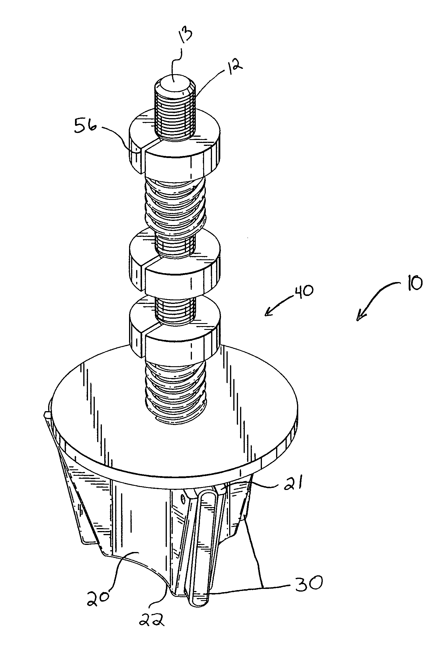
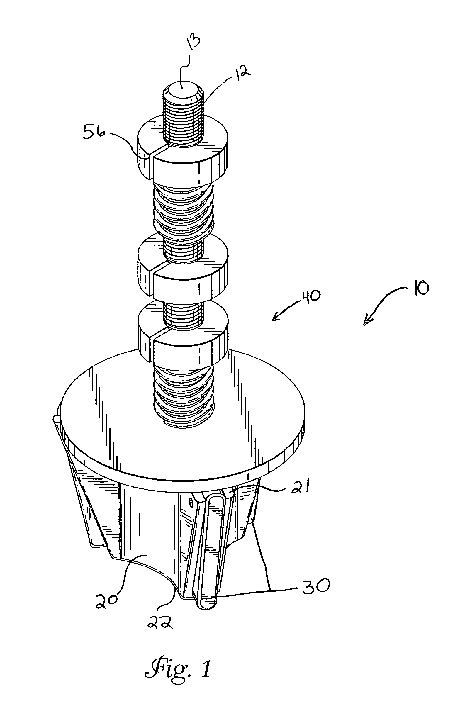
[0021]In an embodiment of the invention, a roll forming apparatus or device is provided, as shown generally at 10 in FIG. 1, the device being capable of forming a multi-lobed roll from a unit of dough. In an example embodiment, the roll forming apparatus of the invention comprises a head member disposed on a shaft member for supporting the head member above a baking container having a bottom wall and at least one peripheral wall. The head member has a plurality of outwardly radiating arms and a plurality of guide blades. Each of the guide blades is disposed in an interior of a respective arm and cantilevers between an extended position and a retracted position. A tension assembly is also included for adjusting the resistance of the guide blades from moving from the extended position toward the retracted position. In another embodiment, a securing assembly is mountable about the shaft member for pivotally securing the shaft member to a rack or a supporting plate above a baking pan.

[0...


PUM

PropertyMeasurementUnit
Lengthaaaaaaaaaa
Electrical resistanceaaaaaaaaaa
Tensionaaaaaaaaaa

Abstract

A roll forming apparatus having a shaft member for supporting a head member above a baking container housing a dough mass. The head member can include a plurality of arms with corresponding guide blades disposed therein for contacting a peripheral wall of the container. A tension assembly is mounted about the shaft member for adjusting movement and an outward force of each of the guide blades. Upon insertion in a baking pan, the head member's arms and guide blades divide the dough into a plurality of dough lobes without damaging the container. In a roll forming process, a rack is provided for receiving and transporting the roll forming apparatus over the container. A securing assembly is mountable about the shaft member for permitting the shaft member to resiliently pivot toward a generally perpendicular orientation with respect to the rack after the container pivotally displaces the head member.

Description

REFERENCE TO RELATED APPLICATIONS[0001]This application claims the benefit of priority under 35 U.S.C. § 119(e)(1) of a provisional patent application Ser. No. 60 / 549,044, filed Mar. 1, 2004, which is incorporated herein by reference in its entirety.FIELD OF THE INVENTION[0002]The invention relates to roll forming devices, particularly roll forming devices adapted to form a roll having a plurality of lobes interconnected by a web of dough.BACKGROUND OF THE INVENTION[0003]Bread and dinner roll forming devices, particularly roll forming devices adapted to form a roll having a plurality of lobes have been used. The roll forming devices or stampers typically have a shaft supporting a head or a roll forming body that presses into a ball or mass of dough placed in a baking pan. The roll forming body typically has retractable arms, each of which are coupled to the roll forming body by an internal horizontally oriented spring. Each of the internal springs biases the arms outward and prevent...

Claims


Application Information

Patent Timeline
IPC IPC(8): A21C11/12
CPCA21C11/12A21C11/02
Inventor ZIMMERMANN, CRAIG E.
Owner GENERAL MILLS INC
Learn More