Controlling cyclone efficiency with vacuum interface

a vacuum interface and cyclone technology, applied in the direction of dispersed particle separation, separation processes, coatings, etc., can solve the problems of quick and easy blowing off of what little powder remains from the powder recovery during spraying operations, and achieve the effects of fast and easy cleaning, reduced time required, and high air flow

Inactive Publication Date: 2006-06-29
SHUTIC JEFFREY R +1
View PDF20 Cites 11 Cited by
  • Summary
  • Abstract
  • Description
  • Claims
  • Application Information

AI Technical Summary

Benefits of technology

[0026] The present invention is directed to a new powder coating spray system that is dramatically faster and easier to clean, thereby significantly reducing the time required for a color changeover. In accordance with one aspect of the invention, a powder coating spray system produces a region of high air flow through a spray booth to extract powder overspray from the booth. The high air flow is produced by a low pressure source outside the booth. In one embodiment, a suction duct is positioned above the booth floor and the air flow into and through the duct sucks up powder from the floor and transports it outside the booth to a collection device. Relative rotation between the floor and the duct permits the entire floor to be swept, and in one embodiment the booth is generally cylindrical and the floor is round rotates about a longitudinal axis of the booth. In another embodiment of the invention, the spray booth walls and floor are made of non-conductive composite materials.
[0027] In accordance with another aspect of the invention, powder overspray that is extracted from a spray booth is recovered back to a powder supply that is used to supply powder to the spray guns inside the spray booth. In one embodiment, the extracted powder overspray is separated from the high flow air stream by a cyclone separator. The powder falls into a transfer pan and a vacuum is used to convey the powder from the transfer pan to a vacuum receiver. The powder is then discharged to the feed hopper in the feed center. The use of a vacuum to convey powder from the cyclone to the feed center in effect permits substantially all of the powder overspray to be recovered from the spray booth directly to the feed hopper with minimal dwell or residence time within the cyclone or vacuum receiver subsystems during a spraying operation. What little powder remains from the powder recovery during spraying operations can be quickly and easily blown-off as part of a cleaning and color changeover procedure.
[0028] In accordance with another aspect of the invention, cyclone efficiency may be influenced and improved by applying a negative pressure at an outlet of the cyclone to convey powder to a container. In one embodiment, the container may be the feed hopper to support the application process. In one embodiment, a vacuum pump is coupled to the cyclone outlet. The vacuum pump produces an induced air volume that entrains powder from the cyclone outlet and conveys the entrained powder to the container. The coupling from the vacuum source to the cyclone outlet is air tight during recovery and conveyance. In accordance with another aspect of the invention, cyclone efficiency is influenced by maintaining a predetermined relationship between the static pressure of the cyclone and the induced air volume of the vacuum source. This allows for the negative pressure to entrain the powder located at the cyclone yield outlet and recover additional powder at the container that would otherwise be lost through the cyclone exhaust (sometimes referred to in the art as the tailings exhaust).

Problems solved by technology

What little powder remains from the powder recovery during spraying operations can be quickly and easily blown-off as part of a cleaning and color changeover procedure.

Method used


Image

  • Controlling cyclone efficiency with vacuum interface
  • Controlling cyclone efficiency with vacuum interface
  • Controlling cyclone efficiency with vacuum interface

Examples


Embodiment Construction

[0076] Introduction

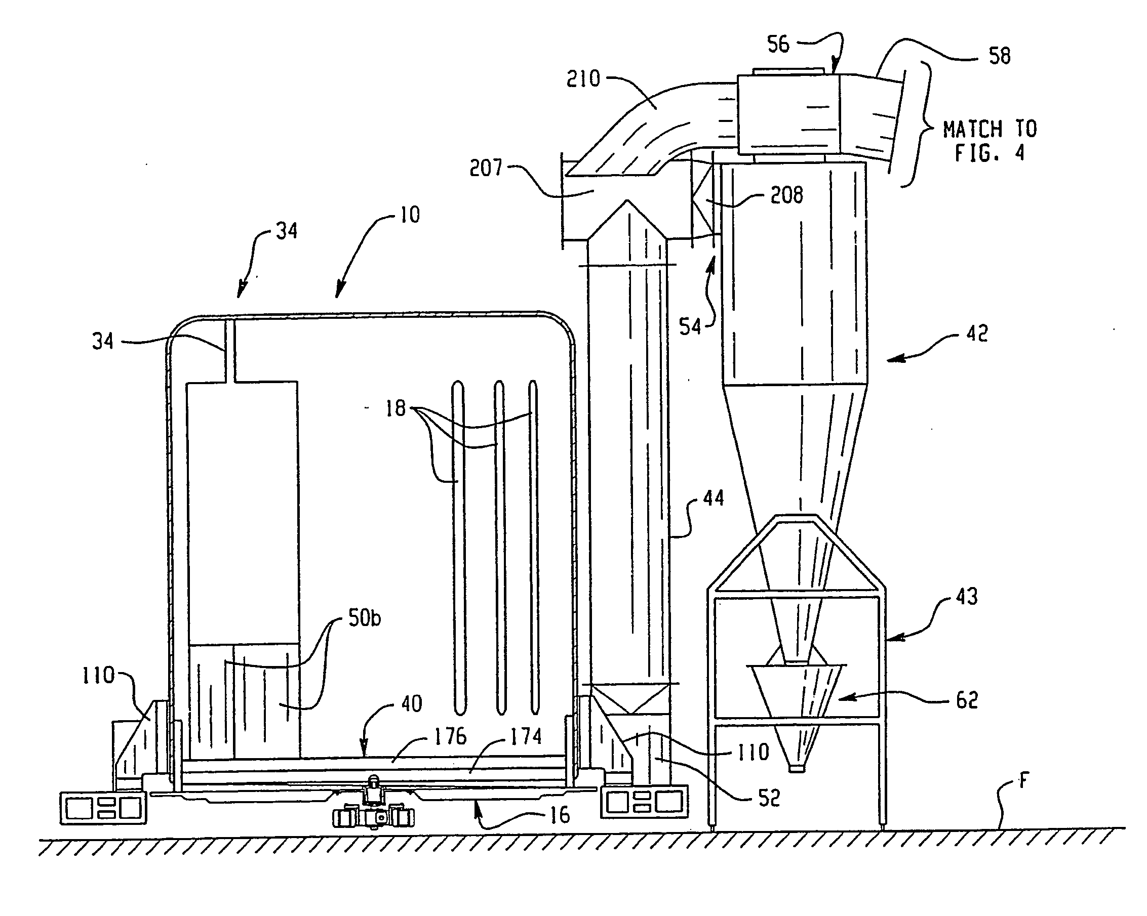
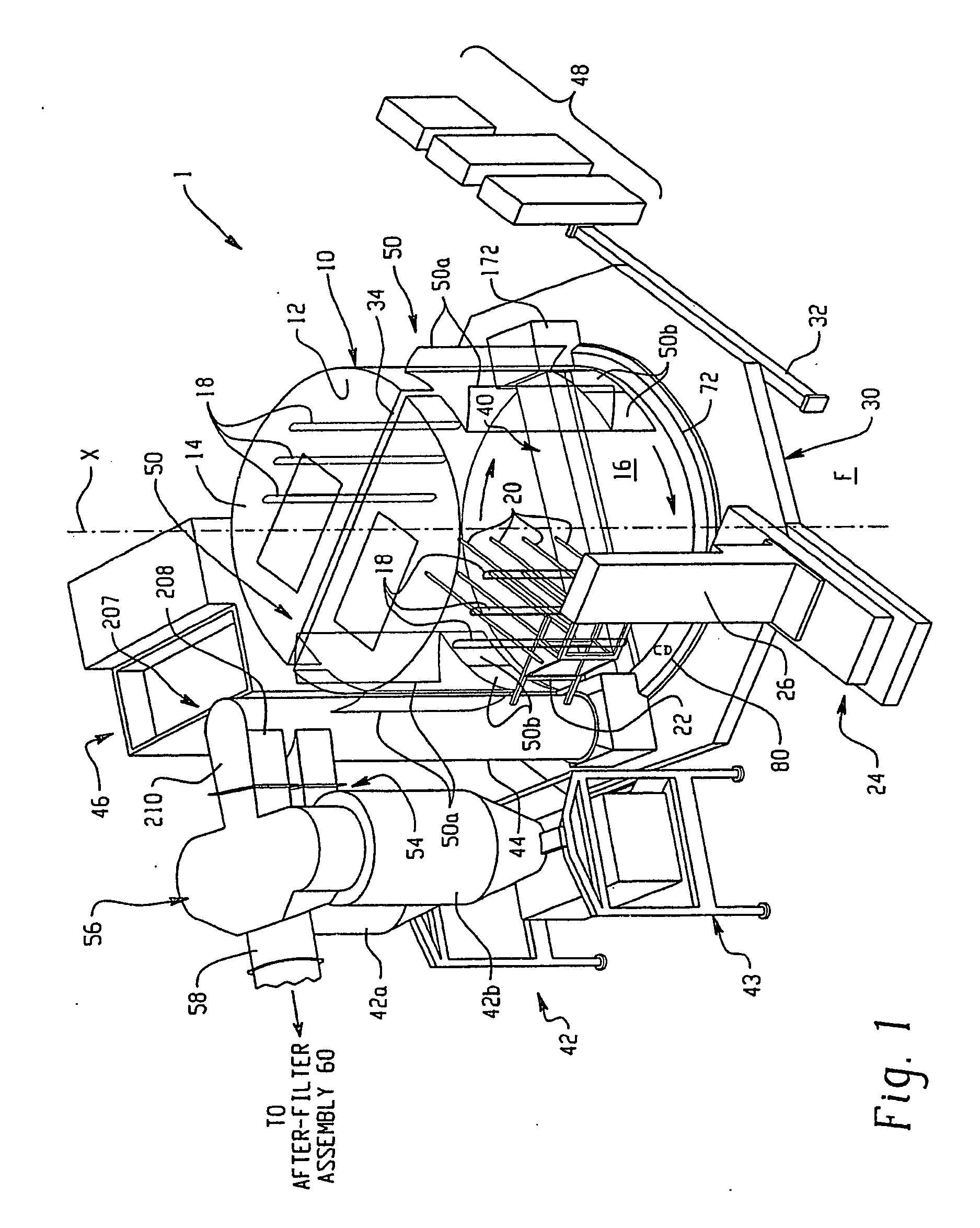
[0077] By way of introduction, the present invention is directed to providing a powder recovery system that takes most of the powder overspray produced in a powder spray booth during a spraying operation and returns it on a real-time basis to the powder feed center. In one embodiment, a powder scavenging protocol is used to recover powder overspray from the spray booth on a continuous basis and return the scavenged powder to the application system on a nearly continuous basis. The powder overspray is also preferably removed from a cyclone separator and returned to the feed center on a continuous basis. By “scavenging” is simply meant the collection and transfer of powder from the time the powder is sprayed by a gun until the powder is returned to the feed center.

[0078] As used herein, the terms “powder recovery” and “powder collection” are used interchangeably. By effectively and continuously recovering most of the powder overspray, cleanup is greatly simplified...


PUM

PropertyMeasurementUnit
rotationaaaaaaaaaa
angleaaaaaaaaaa
diameteraaaaaaaaaa

Abstract

Powder overspray that is extracted from a spray booth is recovered back to a powder supply that is used to supply powder to the spray guns inside the spray booth. The powder overspray extracted from the booth is separated from the high flow air stream by a separator such as a cyclone separator. The powder falls into a transfer pan and a vacuum is used to convey the powder from the transfer pan to a vacuum receiver. The powder is then discharged to the feed hopper in the feed center. The use of a vacuum to convey powder from the cyclone to the feed center in effect permits substantially all of the powder overspray to be recovered from the spray booth directly to the feed hopper with minimal dwell or residence time within the cyclone or vacuum receiver subsystems during a spraying operation. The receiver can be rotated for easy cleaning, and the vacuum line cleaned by one or more cleaning elements drawn through the vacuum line.

Description

RELATED APPLICATIONS [0001] The present application claims the benefit of pending U.S. provisional patent application Ser. No. 60 / 290,447 filed on May 11, 2001 for CONTROLLING CYCLONE EFFICIENCY WITH A VACUUM INTERFACE the entire disclosure of which is fully incorporated herein by reference. The present application is a continuation-in-part of pending U.S. patent application Ser. No. 09 / 888,679 filed on Jun. 25, 2001 for QUICK CHANGE POWDER COATING SPRAY SYSTEM which claims the benefit of U.S. Provisional patent application Ser. Nos. 60 / 277,149 filed on Mar. 19, 2001, and 60 / 238,277 filed on Oct. 5, 2000, the entire disclosures of which are fully incorporated herein by reference.FIELD OF THE INVENTION [0002] The invention relates generally to powder coating spray systems which use powder containment spray booths and power overspray recovery apparatus. More particularly, the invention relates to a powder coating spray system that uses negative pressure to influence cyclone efficiency...

Claims


Application Information

Patent Timeline
Patent Type & Authority Applications(United States)
IPC IPC(8): B01D45/12B05B7/14B05B15/12
CPCB01D45/14B05B7/1454B05B7/1472B05B15/1211B05B15/1214B05B15/1218B05B15/1222B05B15/1229B05B15/1237B05B15/1285B05B14/41B05B14/45B05B14/48B05B16/25B05B16/40B05B16/405B05B16/60Y02P70/10
Inventor SHUTIC, JEFFREY R.KREEGER, KENNETH A.
Owner SHUTIC JEFFREY R
Why Eureka
Try Eureka