
Force estimation for a minimally invasive robotic surgery system

a robotic surgery and force estimation technology, applied in the field of minimally invasive medical procedures, can solve the problems of reduced dexterity and poor tactile perception, limited field of view, and surgeon operating in uncomfortable and tiring posture, and achieve the effect of cost-effective and efficien

Active Publication Date: 2013-01-10
EURO ATOMIC ENERGY COMMUNITY (EURATOM)
View PDF4 Cites 23 Cited by
  • Summary
  • Abstract
  • Description
  • Claims
  • Application Information

AI Technical Summary

Benefits of technology

[0016]The present invention provides a method and system that permit estimation of the force exerted onto, respectively by, the instrument tip in cost-effective and efficient manner while avoiding the need for trocar and / or instrument tip mounted sensors.

Problems solved by technology

The surgeon operates in an uncomfortable and tiring posture, with a limited field of view, reduced dexterity and poor tactile perception.
To these problems adds the fact that surgeons often have to carry out several consecutive interventions per day, each intervention lasting e.g. from 30 minutes to several hours.
In spite of the inherent difficulties, the trend towards minimally invasive procedures is expected to increase further in the coming years due to an increasing average age of the population and pressure of costs in the medical field.
Complications arise inter-alia by the fact that the required posture is often tiresome and reduces the already limited perception of interacting forces between instrument and tissues.
As a result, motorial capabilities of a surgeon normally decay after 20-30 minutes, such that among others trembling, loss of accuracy and loss of tactile sensitivity occur with the resulting risks for the patient.
Currently available teleoperated MIS systems typically do not offer true tactile force feedback (referred to as force feedback below) on the console by means of which the surgeon commands the robot(s).
Hence the surgeon lacks a true haptic feeling of the forces exerted onto organs and tissues.
Such systems have however not yet reach a commercially viable state.
These forces are the main cause of incision wear that can lead to loss of abdominal pressure, release of the trocar, and increased intervention time due to the need to recover the situation.
These detrimental forces are mainly caused by the inaccurate location of the instrument fulcrum (pivot point), as determined by the system and modified due to variations of intra-abdominal pressure, with respect to the patient incision but also by motion drifts of the (robot) manipulator due to its positioning inaccuracy.
This solution does not reduce the risk the incision wear and does not improve the loss of abdominal pressure.
This method and system are not capable of determining the forces at the tip of the instrument inserted through the trocar.
This concept has several drawbacks however, among which manufacturing and installation cost, the lack of robustness in autoclave sterilization, and EMI shielding issues when combined with powered instruments.

Method used


Image

  • Force estimation for a minimally invasive robotic surgery system
  • Force estimation for a minimally invasive robotic surgery system
  • Force estimation for a minimally invasive robotic surgery system

Examples


Embodiment Construction

System Components and Mechanical Configuration

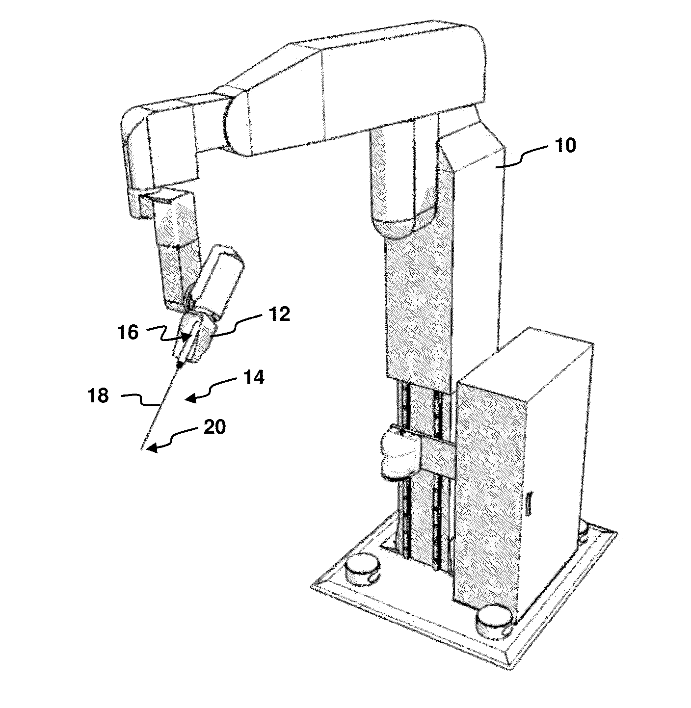
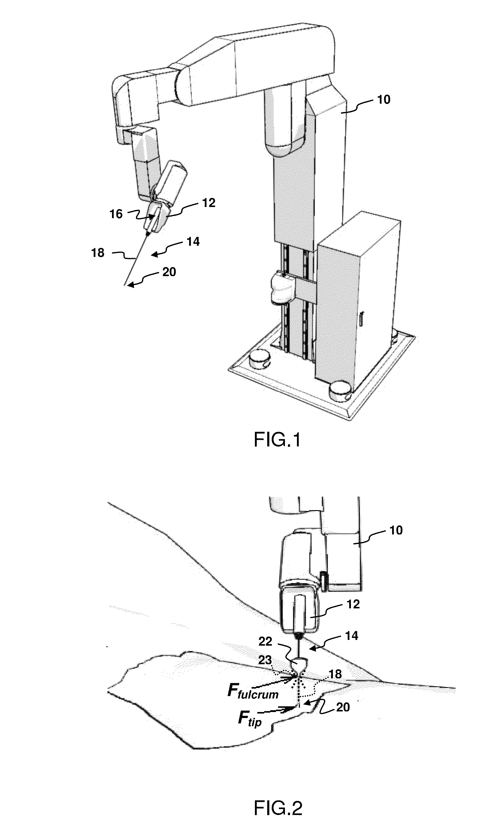
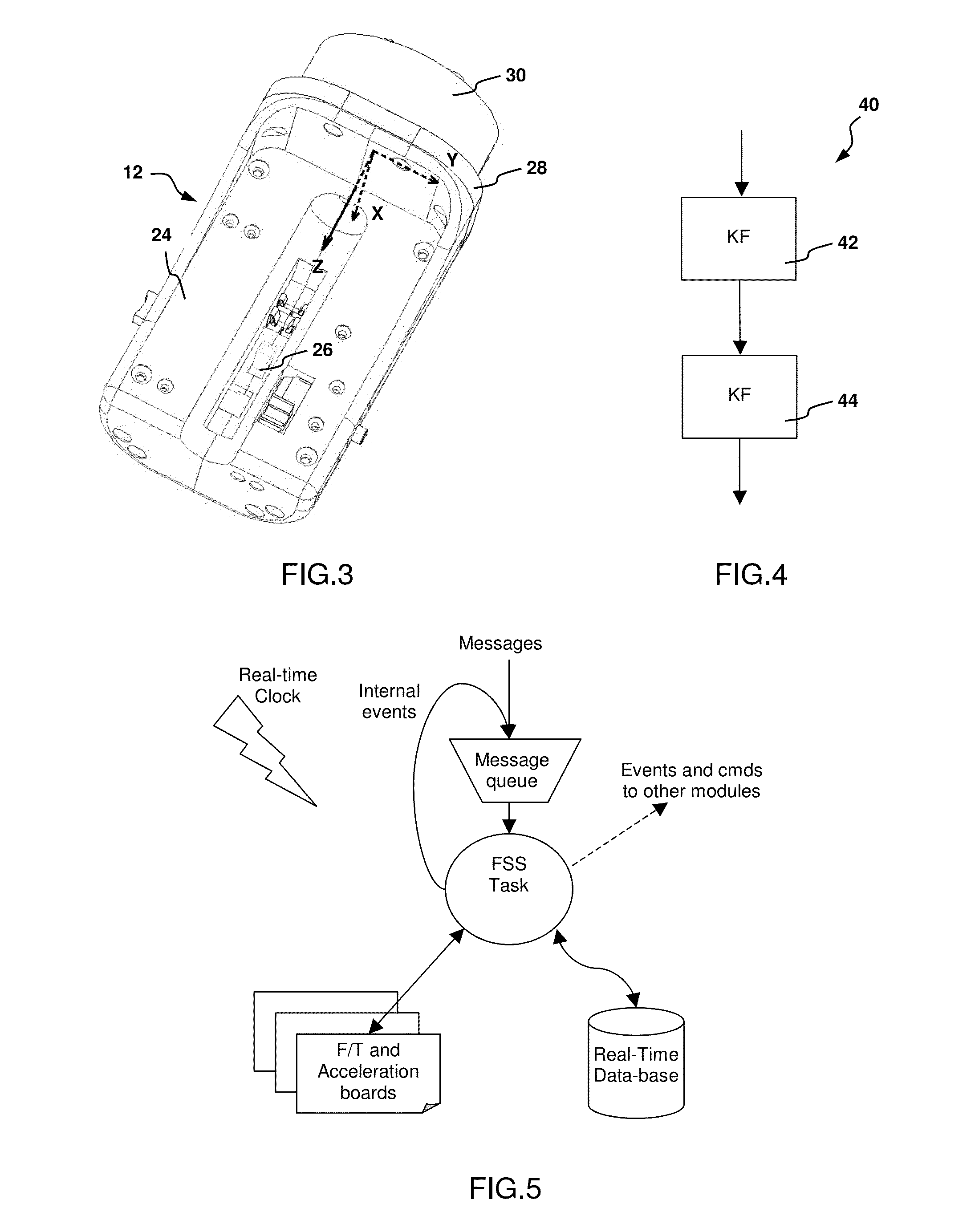
[0054]FIG. 1 shows the main mechanical components of the minimally invasive medical system according to the invention. The system comprises a robot manipulator, generally identified by reference numeral 10. An effector unit 12 is connected to a flange of the manipulator 10. A minimally invasive instrument 14, is mounted with a first end 16 to the effector unit as shown in FIG. 1. The instrument 14 comprises an elongated shaft 18 with a tip 20 forming the second end of the instrument 14. At its tip 20, the instrument 14 normally comprises a specific tool e.g. grasper, scissor, hook, coagulator, etc. The robot manipulator 10 itself provides 6 degrees of freedom (DOF) by means of a PRP-RRR joint arrangement for positioning and orienting the effector unit 12, the effector unit 12 being mounted to the foremost rotational (R) joint for rotating the minimally invasive instrument 14 about the 6th DOF of the manipulator 10 which coincides with th...


PUM


Abstract

A method of force estimation for a minimally invasive medical system including a robot manipulator having an effector unit equipped with a 6-degrees-of-freedom force / torque sensor and being configured to hold a minimally invasive instrument having a first end mounted to the effector unit and a second end located beyond an external fulcrum that limits the instrument in motion, where the method includes determining a position of the instrument relative to the fulcrum, measuring by means of the 6 degrees of freedom force / torque sensor a force and a torque exerted onto the effector unit by the first end of the instrument, and calculating by means of the principle of superposition an estimate of a force exerted onto the second end of the instrument based on the determined position, the measured force and the measured torque.

Description

CROSS REFERENCE TO RELATED APPLICATIONS[0001]This application is a continuation of U.S. patent application Ser. No. 12 / 447,335 filed on 27 Apr. 2009 which is the U.S. national phase of International Patent Application Number PCT / EP2007 / 061494 filed on 25 Oct. 2007 which claims priority to European Patent Application Number 06122937.3 filed on 25 Oct. 2006, all of which said applications are herein incorporated by reference in their entirety.TECHNICAL FIELD OF THE INVENTION[0002]The present invention generally relates to the field of minimally invasive medical procedures, including surgery and diagnostic procedures. More particularly, the invention concerns a method and a system for force estimation that are capable of determining forces exerted onto a patient, especially by the tip of a minimally invasive instrument, but also at the level of the access port for the instrument into the patient body.BACKGROUND OF THE INVENTION[0003]It is well known that minimally invasive intervention...

Claims


Application Information

Patent Timeline
Patent Type & Authority Applications(United States)
IPC IPC(8): A61B17/00
CPCA61B19/22A61B19/2203A61B19/50B25J13/085A61B2019/2292A61B2019/462A61B2019/464A61B2019/223A61B34/30A61B34/35A61B34/70A61B34/76A61B34/10A61B2090/062A61B2090/064B25J9/04
Inventor RUIZ MORALES, EMILIOCORRECHER SALVADOR, CARLOS
Owner EURO ATOMIC ENERGY COMMUNITY (EURATOM)
Learn More