

Dynamic power management system for universal serial bus (USB) hub and method thereof
a technology of power management system and universal serial bus, applied in the direction of power supply for data processing, instruments, measurement devices, etc., can solve the problems of inconvenient situation, inability to operate new products, and inability to correctly operate electronic products, so as to save the cost of external power sources
- Summary
- Abstract
- Description
- Claims
- Application Information
AI Technical Summary
Benefits of technology
Problems solved by technology
Method used
Image

Examples
first embodiment
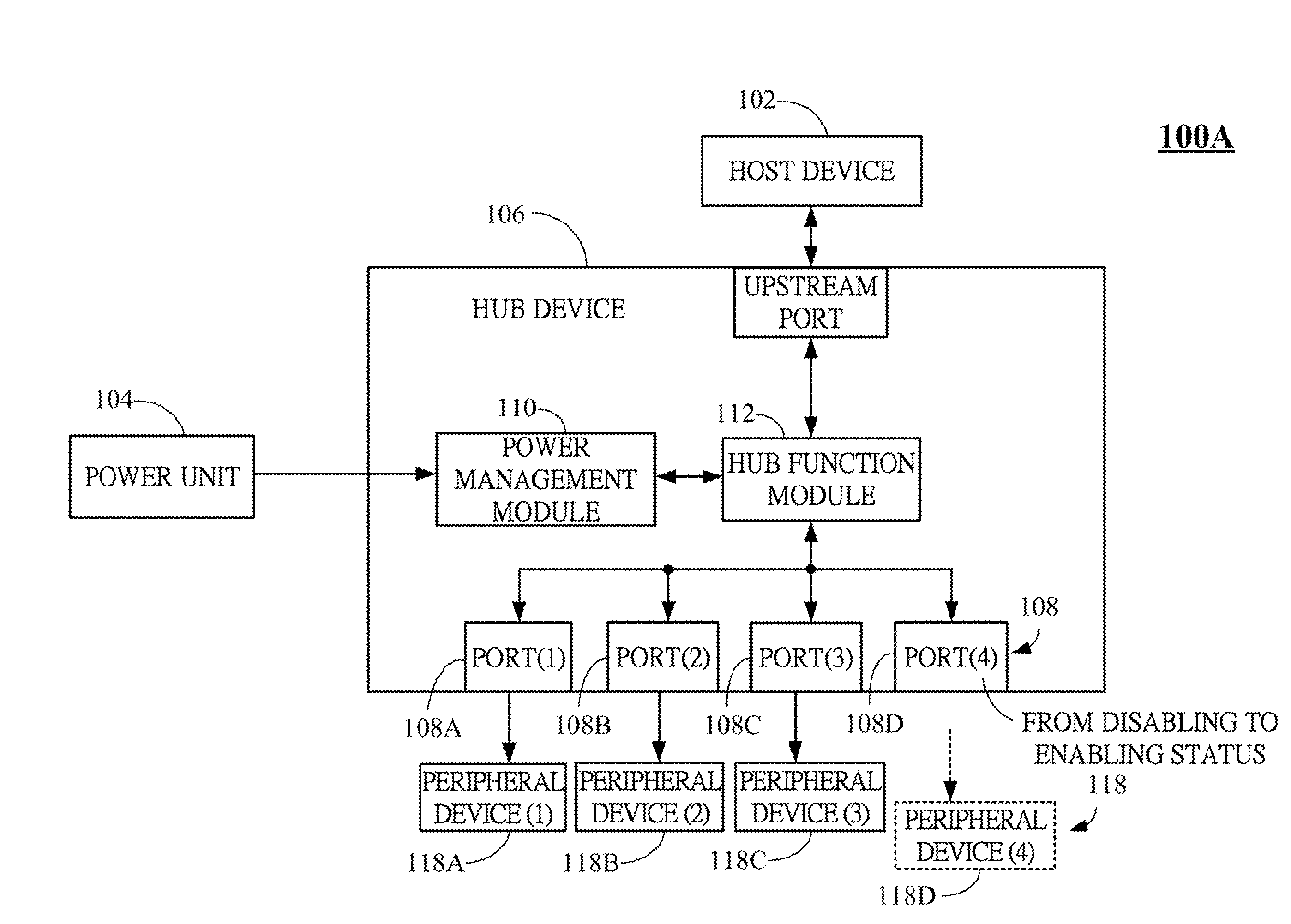
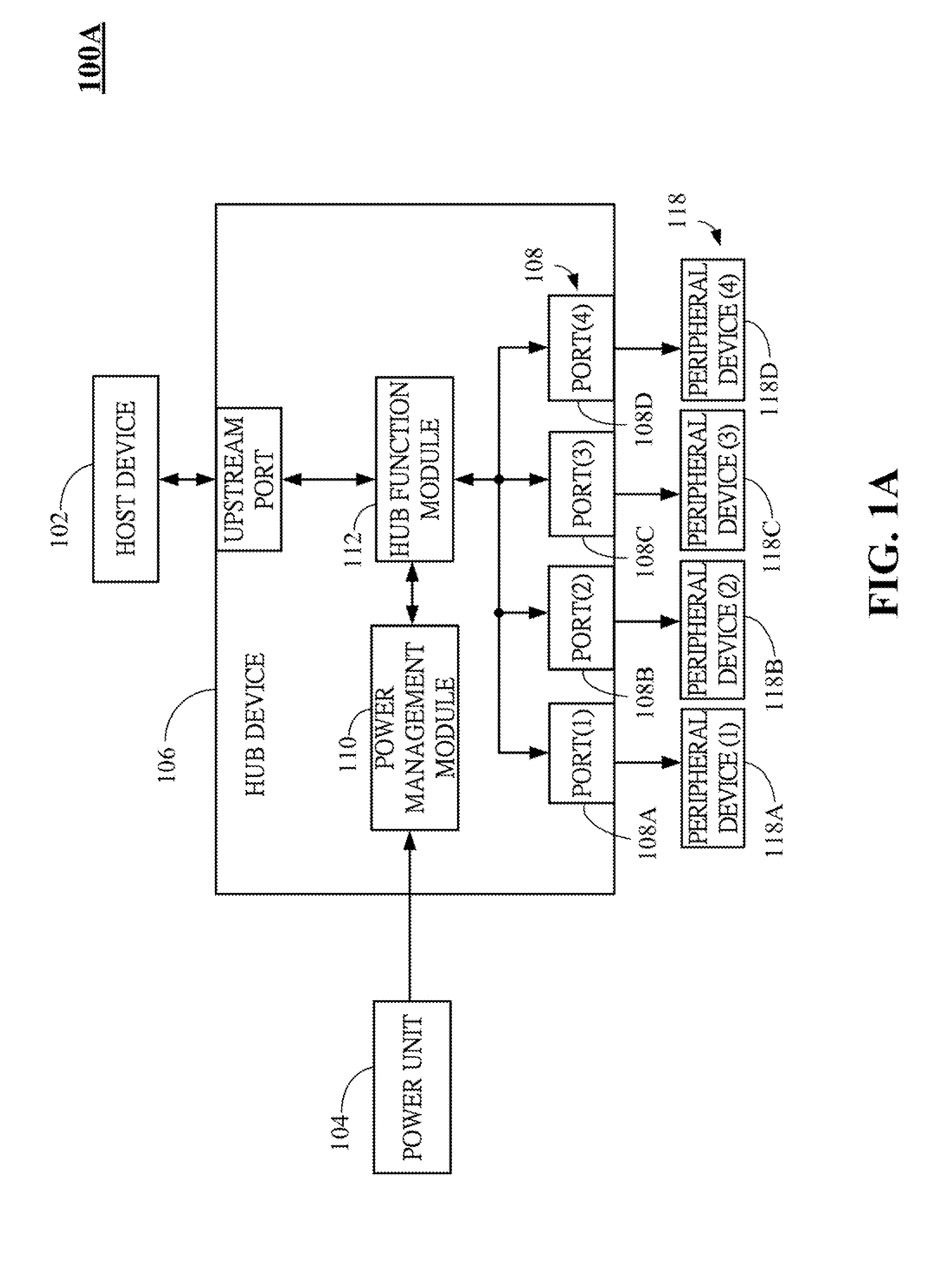
[0031]FIG. 1A is a schematic block diagram of a dynamic power management system 100A for universal serial bus (USB) hub according to the present invention. The dynamic power management system 100A includes a host device 102, a power unit 104 and a hub device 106, e.g. a universal serial bus (USB) hub device. The USB hub device 106 is coupled to the host device 102 and the power unit 104, respectively. The power unit 104 may be an external power source and / or battery for providing a supplying current. The USB hub device 106 establishes a communication link to the host device 102 and receives the supplying current from the power unit 104. In another embodiment, the host device 102 may be another USB hub device (not shown) so that USB hub device 106 can receive the commands from or transmit the messages to the upstream host device (not shown) via another USB hub device (not shown).
[0032]The USB hub device 106 further includes a plurality of ports 108, a power management module 110 and ...
second embodiment
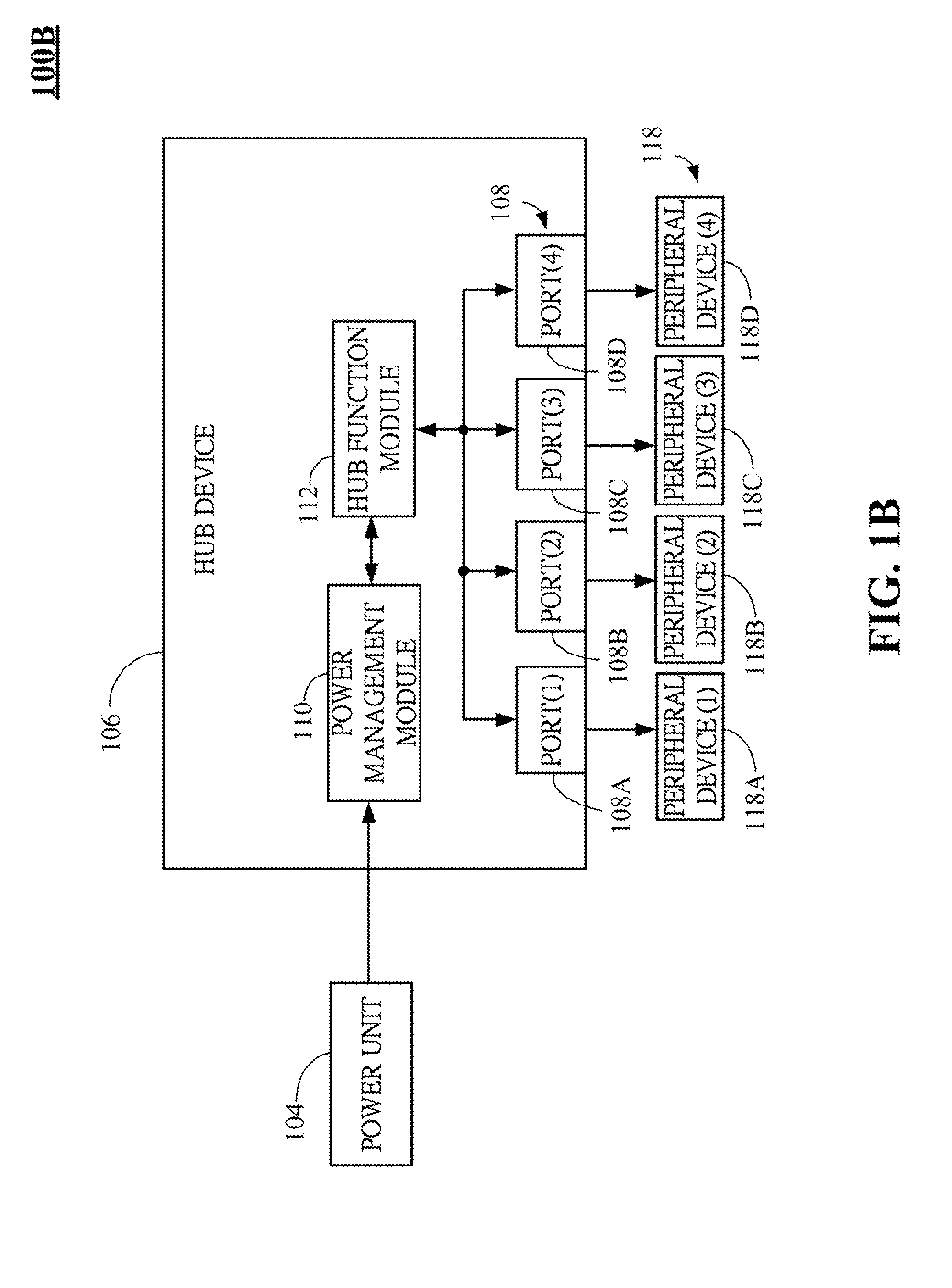
[0036]FIG. 1B is a schematic block diagram of a dynamic power management system 100B for universal serial bus (USB) hub according to the present invention. The dynamic power management system 100B in FIG. 1B is similar to the dynamic power management system 100A in FIG. 1A. The difference is that the host device 102 and the upstream port 108E in the dynamic power management system 100B are omitted and the power unit 104 only provides the supplying current to the USB hub device 106. In one case, the USB hub device 106 may be a USB hub compound or USB OTG (on-the-go) device. The rest components of the dynamic power management system 100B are the same as these of the dynamic power management system 100A, which are omitted here.
[0037]Please refer to FIG. 2A and FIG. 3A. FIG. 2A is a schematic block diagram of a dynamic power management system 100A for universal serial bus (USB) hub and the downgraded execution mode thereof according to one embodiment of the present invention. FIG. 3A is...
PUM
 Abstract
Description
Claims
Application Information