Corner key and frame assembly

a technology of corner key and frame assembly, which is applied in the direction of fastening means, rod connections, mechanical devices, etc., can solve problems such as the difficulty of assembly process

Active Publication Date: 2013-01-24
AU OPTRONICS CORP
View PDF37 Cites 11 Cited by
  • Summary
  • Abstract
  • Description
  • Claims
  • Application Information

AI Technical Summary

Problems solved by technology

Since the side frame 10 usually has burrs after being cut and assembly of the corner key 12 and the s

Method used


Image

  • Corner key and frame assembly
  • Corner key and frame assembly
  • Corner key and frame assembly

Examples


Embodiment Construction

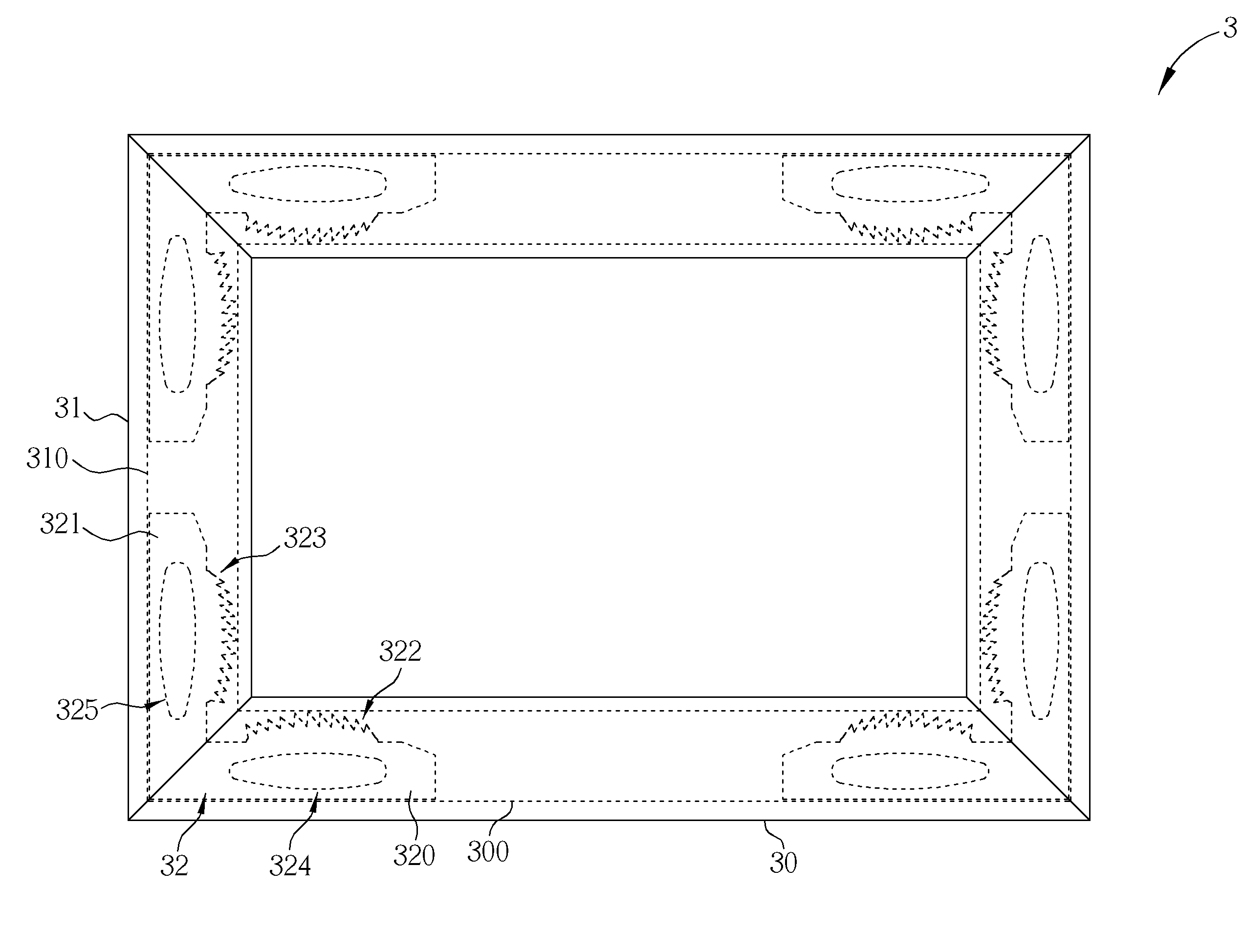
[0020]Please refer to FIG. 3 and FIG. 4. FIG. 3 is a diagram of a corner key 32 according to an embodiment of the present invention. FIG. 4 is a diagram of a frame assembly 3 utilizing the corner key 32 in FIG. 3. As shown in FIG. 3, the corner key 32 includes a first body 320, a second body 321, a first engaging portion 322, and a second engaging portion 323. The second body 321 is connected to the first body 320. An angle α is included between the first body 320 and the second body 321 to make the first body320 and the second body 321 form an L-shaped structure cooperatively. The first body 320 has a first slot 324, and the second body 321 has a second slot 325. The first engaging portion 322 is disposed on the surface of the first body 320 corresponding to the first slot 324. The second engaging portion 323 is disposed on the surface of the second body 321 corresponding to the second slot 325.

[0021]As shown in FIG. 4, the frame assembly 3 includes two first side frames 30, two se...


PUM


Abstract

A corner key includes a first body and a first engaging portion. The first body has a first slot. The first engaging portion is disposed on a surface of the first body and a position of the first engaging portion is corresponding to the first slot. The first engaging portion has a first section, a second section and a third section, wherein the first and third sections are located at opposite sides of the first engaging portion, the second section is located between the first and third sections, and a height of the second section is greater than that of the first section or the third section.

Description

BACKGROUND OF THE INVENTION[0001]1. Field of the Invention[0002]The present invention relates to a corner key and a frame assembly, and more specifically, to a corner key having a slot formed thereon corresponding to an engaging portion of the corner key and a frame assembly utilizing the corner key.[0003]2. Description of the Prior Art[0004]Please refer to FIG. 1 and FIG. 2. FIG. 1 is a diagram of a corner key 12 according to the prior art. FIG. 2 is a diagram of a frame assembly 1 utilizing the corner key 12 in FIG. 1. As shown in FIG. 1, the corner key 12 includes two bodies 120 which are connected to each other and form an L-shaped structure cooperatively. A tooth structure 122 is disposed on the surface of each body 120 respectively. As shown in FIG. 2, the frame assembly 1 includes four side frames 10 and four corner keys 12. Each two adjacent side frames 10 are assembled with one corner key 12 respectively.[0005]In general, the corner key 12 is usually formed by an aluminum e...

Claims


Application Information

Patent Timeline
IPC IPC(8): E04C2/38F16B3/00
CPCE06B3/9644Y10T403/555Y10T403/725E06B3/9645F16B2200/65
Inventor TSENG, HUANG-CHI
Owner AU OPTRONICS CORP
Why Eureka
Try Eureka