Snap-on securement clip for hanging objects from ceiling rails

a technology for securement clips and objects, applied in the field of securement clips, can solve the problems of complicated manufacturing, difficult fixation, and increased cost of fixings

Inactive Publication Date: 2006-06-27
VISUAL CREATIONS INC
View PDF16 Cites 10 Cited by
  • Summary
  • Abstract
  • Description
  • Claims
  • Application Information

AI Technical Summary

Benefits of technology

[0012]In one preferred embodiment a connector plug is comprised of an elongated shaft having an enlarged first end and an oval or ring shaped second or lower end. The enlarged first end is disposed through the connector port to expand and secure the connector plug to the butterfly clip. In this embodiment of the connector plug, a central shaft between the uppermost end and the connector ring has the elongated slot therethrough. The elongated slot permits collapsibility of a portion of the enlarged head so as to permit that enlarged head to be pinched and squeezed through the connector port so as to loosely anchor the connector plug therewithin. The lower end of the connector plug permits capture and connection of a sign (or merchandise) to be hung from the snap-on clip secured to the ceiling rail.
[0017]The weight of any signage and / or merchandise hung utilizing this securement clip is borne by the center section of the clip. Any such weight causes the clip to grip the ceiling rail in a tighter manner, thus creating a very secure attachment arrangement method for grid ceilings.

Problems solved by technology

Such fixtures are often difficult to attach, typically complicated to make and more expensive than necessary.

Method used


Image

  • Snap-on securement clip for hanging objects from ceiling rails
  • Snap-on securement clip for hanging objects from ceiling rails
  • Snap-on securement clip for hanging objects from ceiling rails

Examples


Embodiment Construction

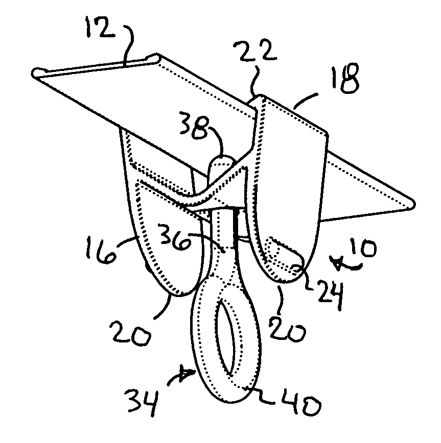
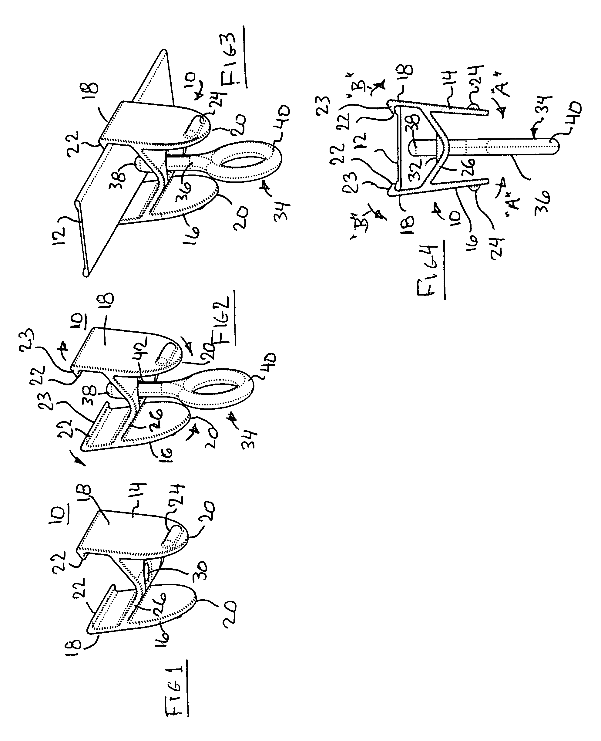
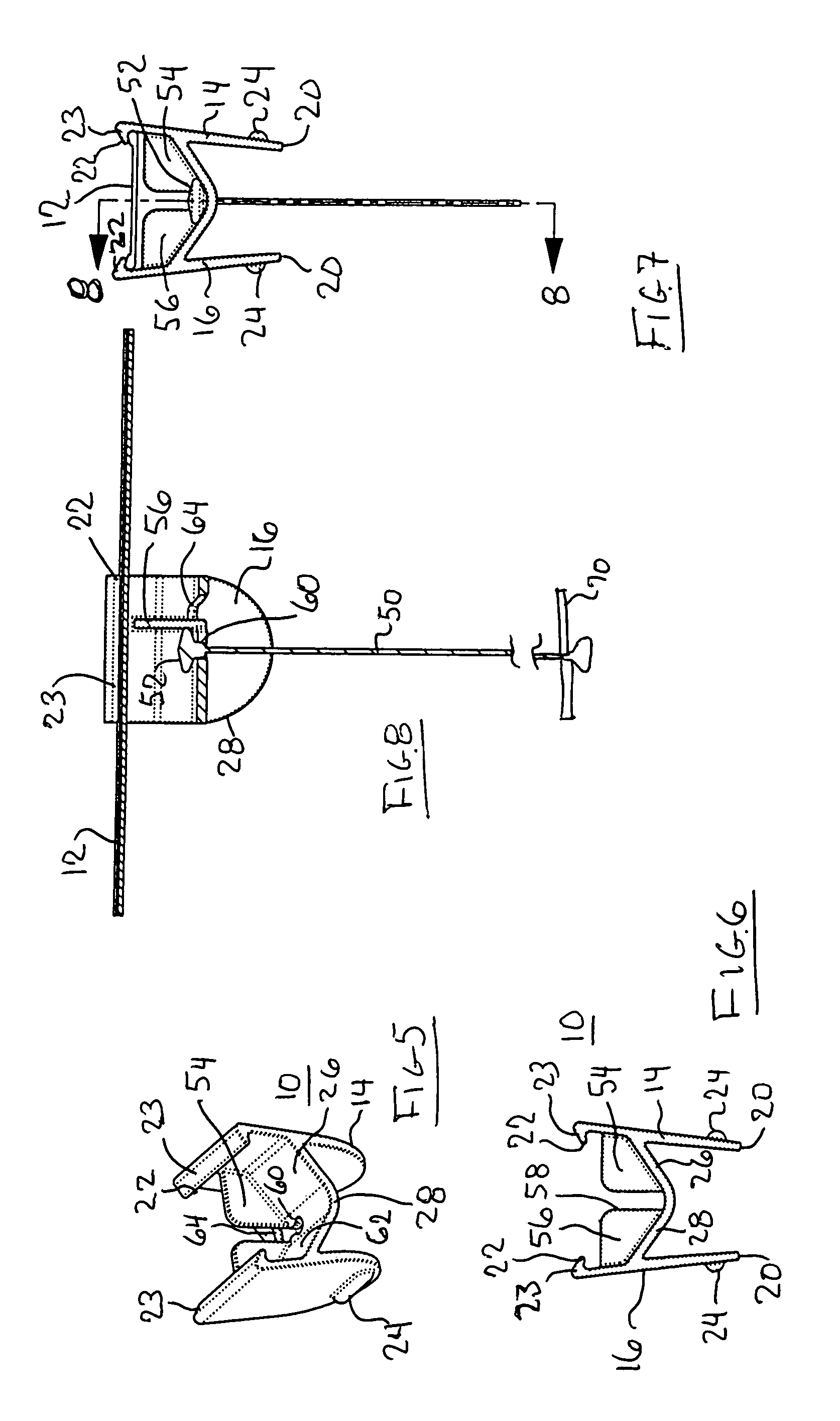
[0032]Referring now to the drawings in detail, and particularly to FIG. 1, there is shown the present invention which comprises a “snap-on” securement clip 10 adapted to be attached onto and removed from a ceiling rail 12, as represented in FIGS. 3, 4, 7 and 8. The snap-on securement clip 10 of the present invention comprises a molded article having an elongated first sidewall 14 and an elongated second sidewall 16. Each elongated first and second sidewall 14 and 16 has an upper end 18 and a lower end 20. Each first and second side wall 14 and 16 has an opposed side lip 22 arranged on its uppermost end 18 and directed towards the other side lip 22, as best seen in FIG. 4. The lips 22 preferably have a tapered outer surface 23, as best shown in FIG. 4, to permit the securement clip 10 to be pivoted onto the ceiling rail 12 by first engagement of one lip 22 onto an edge of the rail 12, then pivoting the sidewall 14 or 16 of that particular sidewall 14 or 16 towards the other sidewall ...


PUM


Abstract

A securement clip for supporting a sign from an overhead ceiling rail comprising a pair of sidewalls arranged to pinch a ceiling rail, a yieldable web connecting the sidewalls, and a hanger connectable to the web. The hanger is arranged to support a sign therefrom. The hanger may be a rigid shaft or a flexible cable. The web is of V-shape in transverse cross section, having a lower apex. The hanger preferably extends through an opening in the lower apex. The sidewalls have an upper edge with a rail engaging lip disposed thereon.

Description

BACKGROUND OF THE INVENTION[0001]1. Field of the Invention[0002]The present invention relates to securement clips, and more particularly to removable clips for supporting a sign or the like from a ceiling rail as may be typically found in a commercial establishment.[0003]2. Prior Art[0004]Signs and display cards are used frequently in commercial stores and retail establishments to indicate location of goods, prices and the like. Such signs need to be displayed in an out of the way yet very noticeable location. Such signs are displayed on posts or walls or from fixtures that may be secured to a ceiling rail. Such fixtures are often difficult to attach, typically complicated to make and more expensive than necessary.[0005]Ceiling rails are found in most commercial establishments. They typically comprise a steel strap approximately one inch wide and they're also utilized to support ceiling panels. Such ceiling rails are typically in the shape of an inverted T.[0006]It is an object of t...

Claims


Application Information

Patent Timeline
Patent Type & Authority Patents(United States)
IPC IPC(8): G09F7/22
CPCG09F3/20G09F7/18G09F2007/186
Inventor PITCHER, DAVID
Owner VISUAL CREATIONS INC
Why Eureka
Try Eureka