Ultra stable optical element x,y, positioning unit for use in harsh environments

a technology of positioning unit and optical element, applied in the field of precise alignment of optical elements, can solve the problems of insufficient robustness of laboratory alignment fixtures when used outside the laboratory, affecting the previously made adjustments, and the typical deployment of these types of hinges is not particularly well suited, etc., to achieve the effect of reducing the thermal resistance of the clamping plate, reducing the area, and high pressur

Inactive Publication Date: 2006-05-04
BAE SYST INFORMATION & ELECTRONICS SYST INTERGRATION INC
View PDF5 Cites 10 Cited by
  • Summary
  • Abstract
  • Description
  • Claims
  • Application Information

AI Technical Summary

Benefits of technology

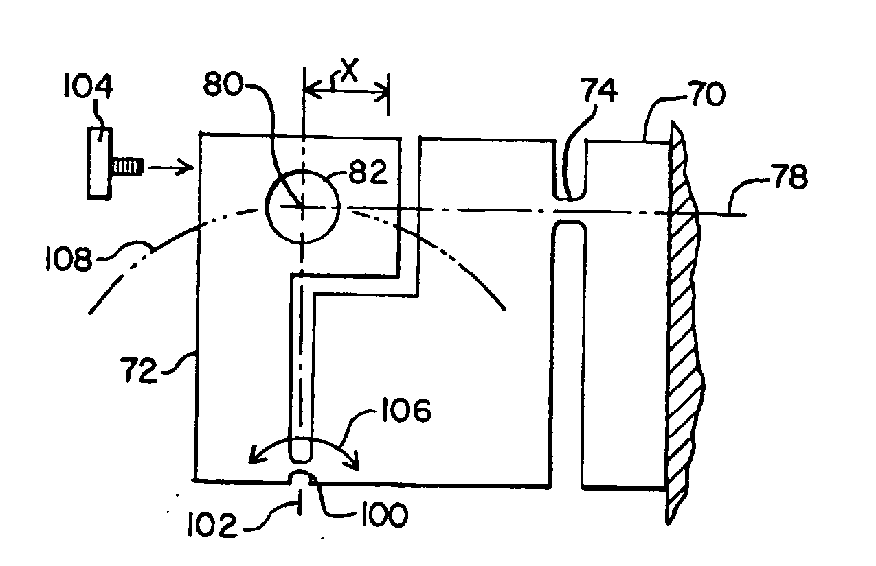
[0019] The structure thus formed in essence is a single unitary structure with the positions of the individual parts maintained through friction formed by the high clamping pressure of the plates. The clamping is arranged so that there is no loading of the parts in directions that affect the alignment prior to clamping. Moreover, the material of which the clamping plates are made matches the thermal coefficient of expansion of the block so that changes in temperature affect all parts of the structure identically. The structure with the locking plates being made of the same material react identically to temperature changes, with structural rigidity of the structure resisting alignment changes in the face of dynamic and static loading. Furthermore, the relatively large area and high pressure achieved in the clamping action acts to reduce the thermal resistance from the clamping plates to the block, effectively reducing the occurrence of temperature gradients across the unit and enhancing stability.
[0021] High stress may be developed in the tiny hinge region during adjustment near the extreme ends of the adjustment range, which is usually not more than a few degrees. This high stress is not a detriment to the functioning of the unit, because the locking sandwich around the adjustable block forms a clamped, laminate structure that is very strong. Even in the case where the stress is locked in by the clamps, causing creep to occur in the hinge over time, the clamping plates so tightly grip the adjustable element that the force induced there can be ignored. This is true in part, because the tiny hinge region, where the stress is high, is very small with respect to the adjustable element. This relatively small aspect ratio of hinge area to clamped area keeps the high stress from causing high force or what would be perceived as high force by such a large clamp. Instead, the high stress is able to manifest itself as harmless creep in the hinge, until the clamp is released at some future time, if it is ever released at all. In other words, if the creep strength of the material is exceeded during adjustment the unit might exhibit a shift in adjusted position at some future date when un-clamped. This will not affect the accuracy, resolution or stability of the unit if the clamping plates are deployed and left in place.

Problems solved by technology

The typical deployments of these types of hinges are not particularly well suited for harsh environments because they are usually designed for use in a laboratory, in which the conditions are carefully controlled as to temperature, humidity and mechanical stress.
If they do, the lock down mechanisms deleteriously affect the previously made adjustments.
Moreover, laboratory alignment fixtures are not sufficiently robust when used outside the laboratory such as for laser target designators, communications systems involving lasers or in surveying equipment.
Additionally, unless ruggedized and specially designed, laboratory fixturing apparatus for the alignment of optical elements is unacceptable for military and commercial applications because optical alignment is severely affected by changing environmental conditions.
If the laser designated spot is displaced by a significant amount, for instance 20 feet, then the ordinance may miss its target altogether.
Thus it is possible that either a tank will not be properly illuminated or that a missile silo can be missed.
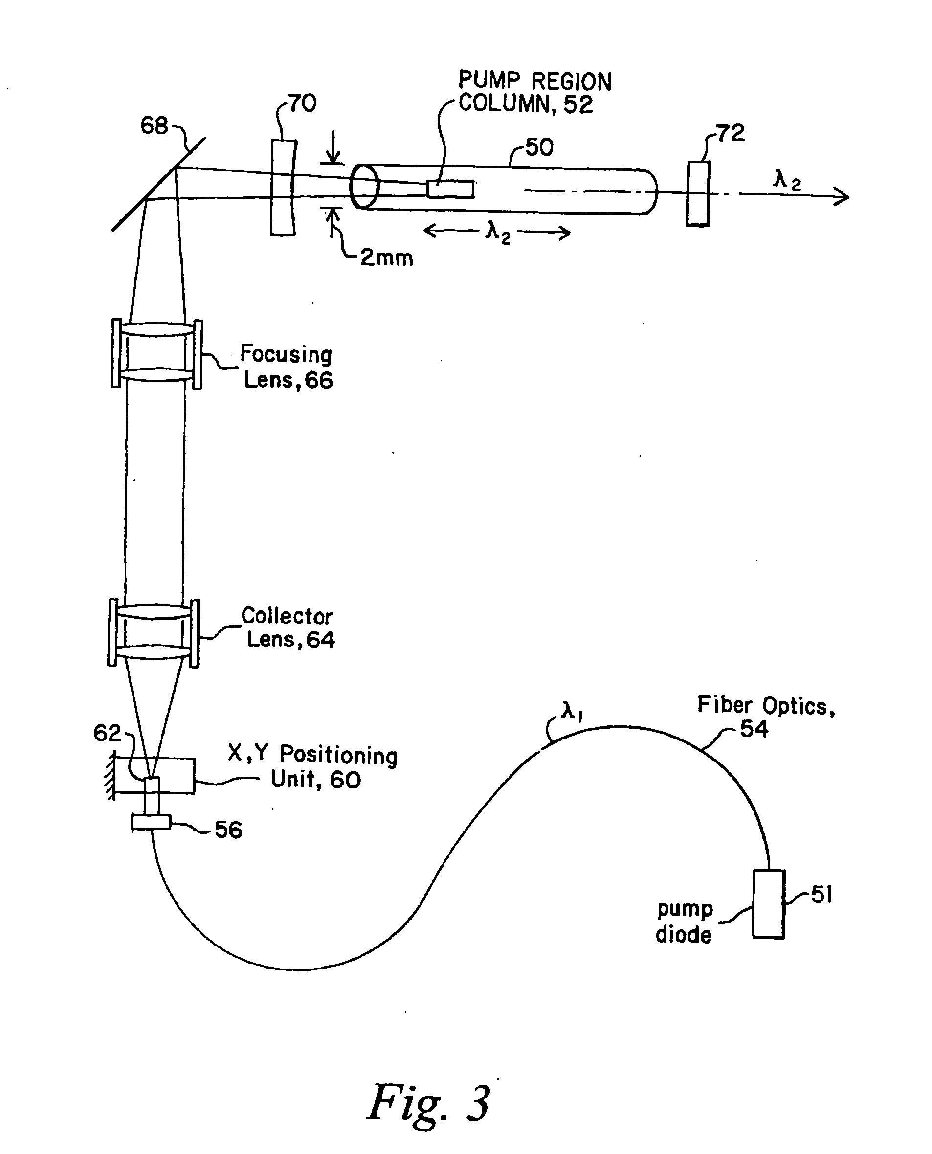
This focusing operation is highly critical, with any off centering of the pumped radiation in the laser rod causing a loss of laser power and boresight alignment.
The heat generated by the pumping laser is sometimes referred to as self-contamination, which can cause a shift of the optical elements resulting in boresight error.
So precise is the positioning requirement for the end of the fiber optic cable that lateral movement of the cable of greater than one half-micron results in reduced laser power, and possibly boresight error, due to movement of the focused radiation, and thus the pump region within the laser rod.
When, for instance, providing laser communications between an over flying satellite and an earth station, any positioning errors will affect the receipt of information contained on the beam.

Method used


Image

  • Ultra stable optical element x,y, positioning unit for use in harsh environments
  • Ultra stable optical element x,y, positioning unit for use in harsh environments
  • Ultra stable optical element x,y, positioning unit for use in harsh environments

Examples


Embodiment Construction

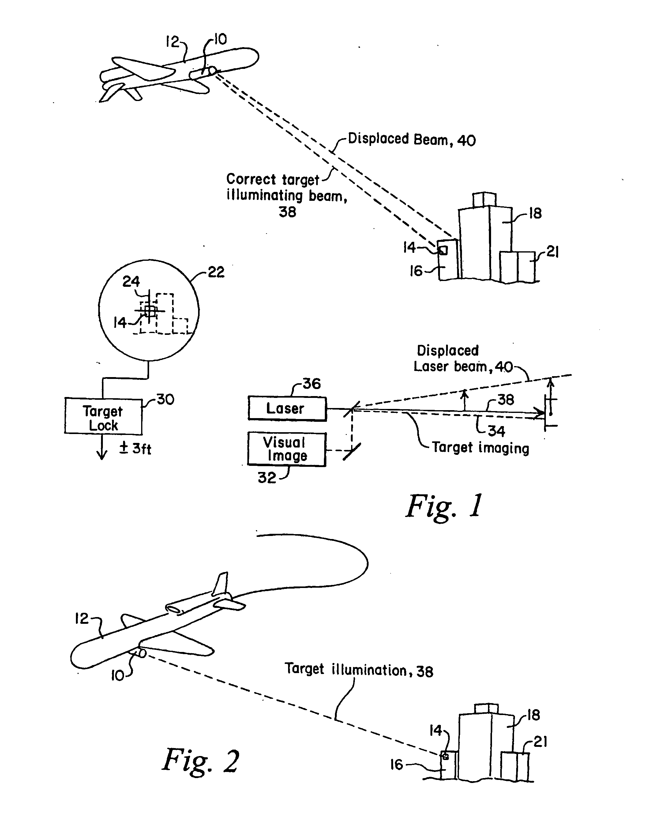
[0034] Referring now to FIG. 1, in a tactical situation an airborne laser target designator 10 is carried by an aircraft 12 which is utilized to illuminate a target 14 which may be a particular window in a building 16 surrounded, for instance, by a stack 18 and an outlying building 21.

[0035] During the laser target designator process, the aircraft, which may be standing off by as much as one mile, acquires the visual image of the target on a screen 22 having a crosshair in the center thereof. The entire optical system is maneuvered around so as to visually center the illuminated target, namely window 14 on crosshairs 24. When the crosshairs designates the intended target, a target lock system 30 is engaged to have the laser target designator lock onto the target, in this case window 14, at which point a laser beam is projected towards the target.

[0036] The laser target designator includes a visual image system 32, which has as its boresight dotted line 34. It will be appreciated t...


PUM


Abstract

An X, Y positioning unit, mount or fixture is designed to adjust the position of an optical element mounted in the fixture so as to move it laterally and vertically with respect to the optical axis of the element, such that, once adjusted, the position is maintained through the clamping of plates about the positioning fixture to lock the hinges against movement. In this manner the adjusted position of the optical element is locked with high forces exerted by the plates on the fixture, with the locking technique not affecting the alignment. In one embodiment, the fixture includes live hinges which join an optical element holder to a fixed plate and pivot the holder about orthogonal axes crossing at the center of an optical element holder such that small movements of the hinged holder about the hinges adjusts the position of the center of the optical element holder and thus the optical element. The fixture in a preferred embodiment includes a milled block of metal having slots Electric Discharged Machined or High Speed Machined therein to leave thin flexible hinges, with positioning screws utilized to move the optical element holder about the hinges. When the appropriate adjustment has been made, the holder is clamped in the adjusted position to the fixed plate through the use of the clamping plates to provide a rigid structure capable of withstanding high static and dynamic loading. For laser target designator applications, positioning unit tolerance is less than one half micron, resulting in target designation boresight alignment errors less than 500 microradians.

Description

FIELD OF INVENTION [0001] This invention relates to optical alignment equipment and more particularly to a method and apparatus for precisely aligning optical elements and maintaining the alignment in the presence of harsh environments. BACKGROUND OF THE INVENTION [0002] It will be appreciated that optical alignment systems have included flexible hinge type mechanisms for positioning the optical axis of an optical element through flexure of live hinges. By live hinges, what is meant is a necked-down area on a solid object, being made thin enough that it forms a flexure, allowing one solid portion of the object to move with respect to the solid portion on the opposite side of the necked down region. This movement is pure rotation about the hinge, but for a small angle approximates linear motion. Usually, the elastic limit of the material from which the object is made will allow a few degrees of motion before plastic deformation occurs. Sometimes plastic deformation of the live hinge ...

Claims


Application Information

Patent Timeline
Patent Type & Authority Applications(United States)
IPC IPC(8): G02B6/26G02B6/32G02B6/36G02B6/42G02B7/00
CPCG02B6/32G02B6/3616G02B6/4226G02B7/003
Inventor WILLIS, CHRISL
Owner BAE SYST INFORMATION & ELECTRONICS SYST INTERGRATION INC
Why Eureka
Try Eureka