
Rolling bearing and crown-shaped retainer

Active Publication Date: 2013-01-24
NTN CORP
View PDF7 Cites 5 Cited by
  • Summary
  • Abstract
  • Description
  • Claims
  • Application Information

AI Technical Summary

Benefits of technology

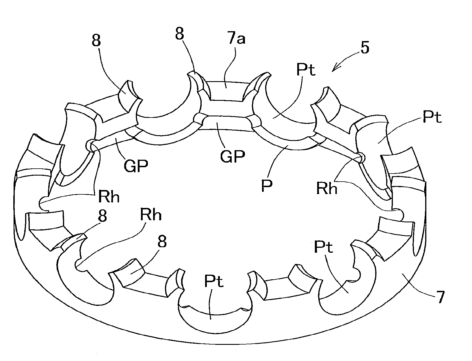
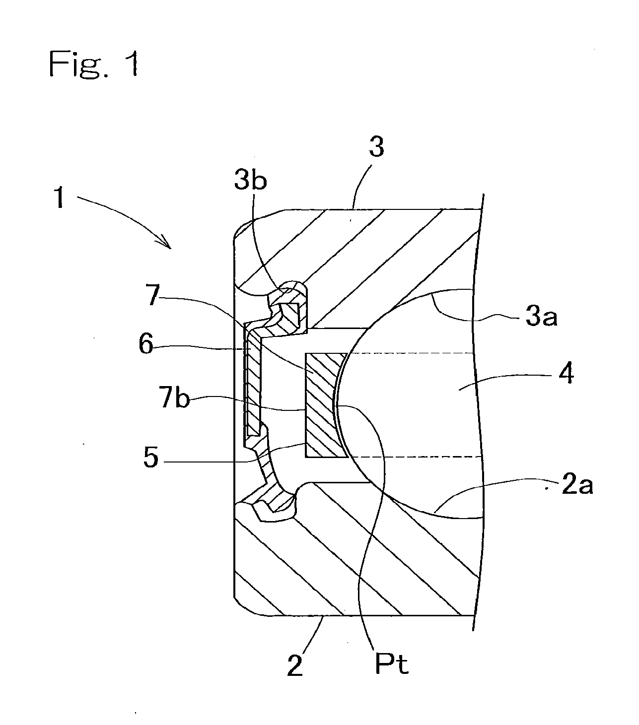
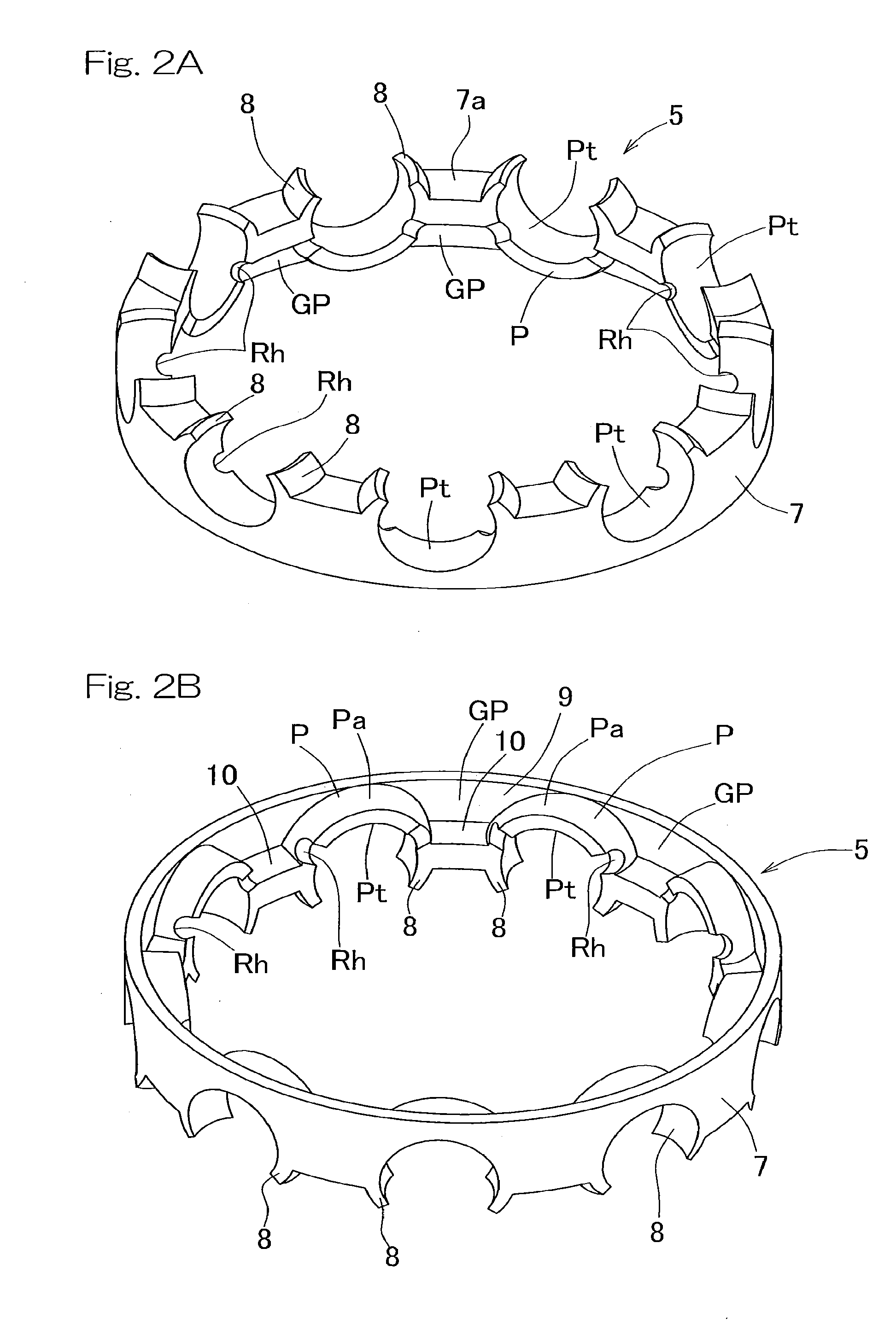
The present invention provides a rolling bearing assembly and a crown shaped retainer that can reduce rotating torque without limitation of the bearing assembly. The grease and sealing member can also be used without any modification. The crown shaped retainer has a communicating port in the form of a cutout opening. The effect of scraping the grease with the edge of the cutout can be increased.

Problems solved by technology

Since depending on the application of the bearing assembly, the grease and / or the sealing member cannot be modified, application of the torque reducing method that is practiced with the grease or the sealing member is limited.
In the other retainers discussed above, since the surface area required to retain the rolling elements decreases, there is the possibility that rocking and rattling may occur.

Method used


Image

  • Rolling bearing and crown-shaped retainer
  • Rolling bearing and crown-shaped retainer
  • Rolling bearing and crown-shaped retainer

Examples


second embodiment

[0077]The retainer designed in accordance with the present invention will now be described in detail with particular reference to FIGS. 11A to 11D. As shown in FIGS. 11A and 11B, a portion of the retainer ring body 7 of the retainer 5, where the corresponding grease reservoir depressed portion GP is defined, may have such a sectional shape, when viewed in a plane containing the axis L1 of the retainer ring body 7, that the corresponding connecting segment 10 in the retainer ring body 7 has an inclined face 10a inclined at an angle relative to a plane S1 orthogonal to the axis L1.

[0078]The inclined face 10a employed in the retainer 5 shown in FIG. 11A is of a structure in which the wall thickness of the corresponding connecting segment 10 is made decreasing in a direction radially inwardly thereof as shown by the arrow A. In this case, the retainer rigidity can be increased as compared with the retainer shown in and described with particular reference to FIG. 4 and the strength of th...

third embodiment

[0080]With reference to FIG. 12 the present invention will now be described in detail. The retainer 5A shown in FIG. 12 is of a structure in which the retainer ring body 7 has another side face 7b of the respective grease reservoir depressed portion GP, which is opposite to the counter pocket side, provided with a cover member 11 for covering the other side face of the grease reservoir depressed portion GP. For example, by means of a machine working utilizing, for example, a machining center, the shape having the cover member 11 can be easily formed. According to this retainer 5A, in the case of a high speed operation, an undesirable leakage of the grease reserved within the respective grease reservoir depressed portion GP can be avoided thanks to the use of the cover member 11.

fourth embodiment

[0081]FIG. 13 illustrates the present invention. The retainer 5B shown therein is of a type manufactured by the utilization of any known injection molding technique, in which each of the communicating ports Rh is so formed as to be flared in a direction from the pocket Pt side towards the adjacent grease reservoir depressed portion GP side. Particularly a counter pocket side portion of each of the communicating ports Rh is so formed as to assume a parallel relation with the axis L1 of the retainer ring body 7. In this case, the retainer 5B can be easily removed from the injection molding mold assembly. Also, a mold on the grease reservoir depressed portion GP side, where a processing is relatively easy to achieve, not on the pocket Pt side where a highly precise processing is required in the mold assembly, can be adopted as a mold for forming the respective communicating ports Rh. Accordingly, the cost required to assemble the mold assembly can be reduced.


PUM


Abstract

A rolling bearing assembly and a crown shaped retainer, in which the rotating torque of the bearing assembly can be reduced with no limitation in use of the bearing assembly and with no need to modify the grease and the sealing member are provided. The rolling bearing assembly includes a plurality of balls interposed between inner and outer rings, and a retainer for retaining the balls. The retainer is of a crown shaped configuration including a retainer ring body having one side face formed with pockets, each having a portion with an opening, defined at respective locations in a circumferential direction for accommodating therein the balls; a grease reservoir depressed portion provided between the neighboring pockets in the circumferential direction of the retainer ring body for reserving a grease; and a communicating port for communicating the grease reservoir depressed portion and the pocket.

Description

CROSS REFERENCE TO THE RELATED APPLICATION[0001]This application is based on and claims Convention priority to Japanese patent application No. 2010-074326, filed Mar. 29, 2010, and Japanese patent application No. 2011-005762, filed Jan. 14, 2011, the entire disclosures of both of which are herein incorporated by reference as a part of this application.BACKGROUND OF THE INVENTION[0002]1. Field of the Invention[0003]The present invention relates to a bearing assembly and a crown-shaped retainer for use in a rolling bearing assembly and, more particularly, to the structure of a retainer capable of providing a low torque.[0004]2. Description of Related Art[0005]Most of ball bearing assemblies currently available are used in a condition with a grease filled therein as a lubricating agent and sealed by a seal or a shield. The bearing assembly utilizing the grease has some advantages in that as compared with the lubrication with oil, no oil supply system is needed, and is hence maintenance...

Claims


Application Information

Patent Timeline
IPC IPC(8): F16C33/66
CPCF16C33/416F16C33/6614F16C33/418F16C19/06F16C33/6629F16C2240/30F16C2300/02F16C2240/42
Inventor KAWAMURA, MITSUOFUJIWARA, HIROKI
Owner NTN CORP
Learn More