Corneal Implant Retaining Devices and Methods of Use

US20130023892A1Inactive Publication Date: 2013-01-24REVISION OPTICS

Image

  • Corneal Implant Retaining Devices and Methods of Use
  • Corneal Implant Retaining Devices and Methods of Use
  • Corneal Implant Retaining Devices and Methods of Use

Examples


Embodiment Construction

[0035]The disclosure relates generally to storage and retention devices for corneal implants. The devices can be used for long term storage of a corneal implant, or can be used for short term storage, such as just prior to an implantation procedure of the corneal implant. β€œCorneal implants” used herein refers to any medical device positioned on or in a cornea, and includes, without limitation, corneal inlays, corneal onlays, and contact lenses.

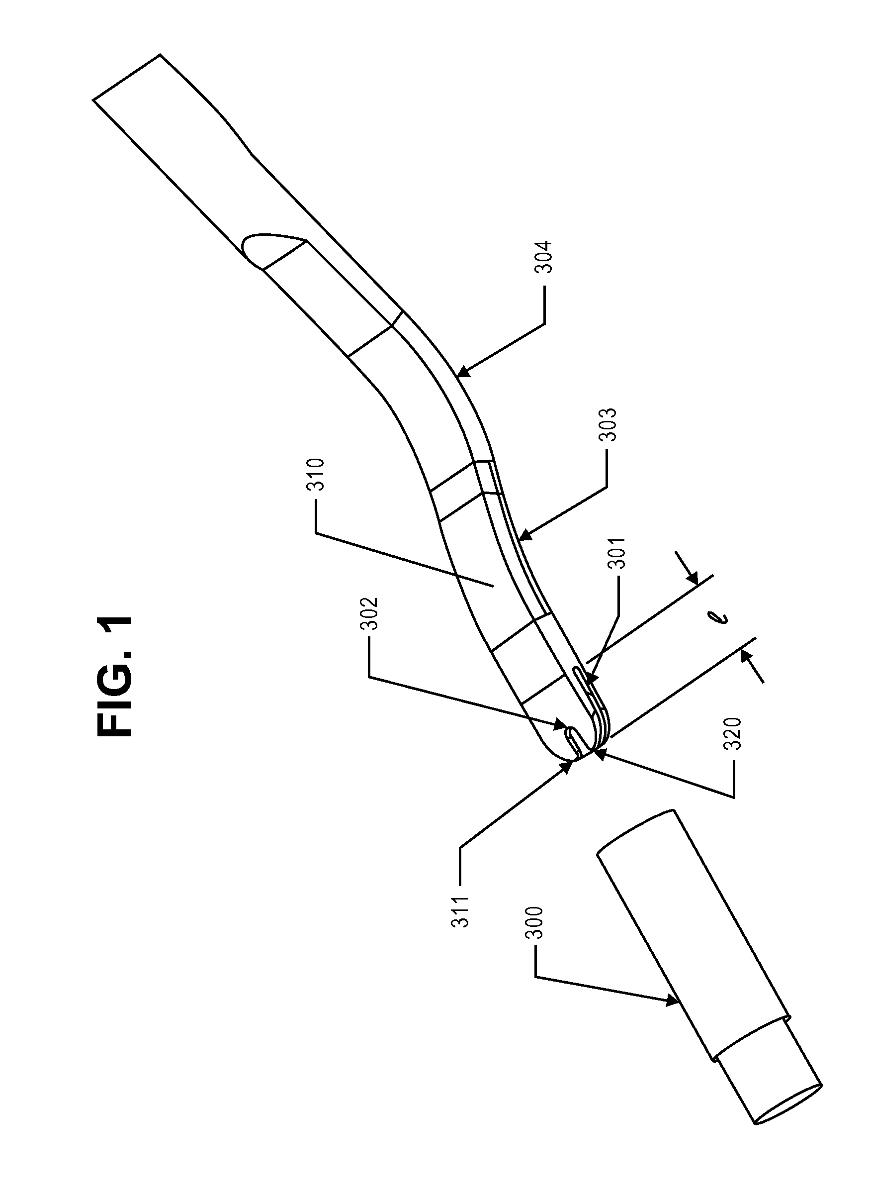
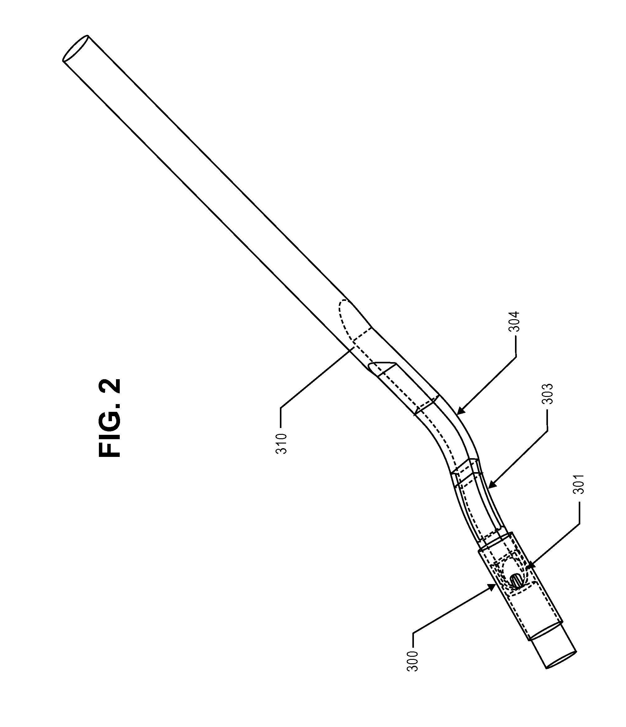
[0036]FIGS. 1 and 2 illustrate an exemplary insertion system that is adapted to deliver a corneal implant, e.g., cornea inlay, in or on the cornea. The insertion system can also be used to store the corneal implant prior to its use. The insertion system includes an inserter 310 having an elongated body, which may be made of titanium, stainless steel, plastic, or other biocompatible material. The inserter 310 comprises a distal portion having generally flat top and bottom surfaces. The distal portion of the inserter 310 includes a clearance ben...


PUM


Abstract

Corneal implant retaining devices and their methods of use. The retaining devices can be a cap adapted to be disposed over a portion of a corneal implant insertion device.

Description

CROSS REFERENCE TO RELATED APPLICATIONS[0001]This application is a continuation-in-part of U.S. application Ser. No. 13 / 411,425, filed Mar. 2, 2012, which application is a continuation of U.S. application Ser. No. 11 / 692,835, filed Mar. 28, 2007, now U.S. Pat. No. 8,162,953, which is incorporated by reference herein.[0002]This application also claims the benefit of U.S. Provisional Application No. 61 / 535,819, filed Sep. 16, 2011, which is incorporated by reference herein.[0003]This application is also related to and incorporates by reference herein the following applications: U.S. Provisional Application No. 61 / 535,744, filed Sep. 16, 2011; U.S. Provisional Application No. 61 / 550,185, filed Oct. 21, 2011; and U.S. Provisional Application No. 61 / 606,674, filed Mar. 5, 2012.INCORPORATION BY REFERENCE[0004]All publications and patent applications mentioned in this specification are herein incorporated by reference to the same extent as if each individual publication or patent applicati...

Claims


Application Information

Patent Timeline
24 Jan 2013
Publication
US20130023892A1
IPC
A61F9/00
CPC
A61F2/146; A61F2/148; A61F2/142
Inventors
SCHNEIDER, NED; LE, ALAN NGOC