Corneal implants and methods and systems for placement

A cornea and implant technology, applied in eye implants, medical science, prostheses, etc., can solve the problem that the transmission system cannot be well adapted to the transmission system

Active Publication Date: 2009-09-02
伊齐耶·舒埃
View PDF9 Cites 9 Cited by
  • Summary
  • Abstract
  • Description
  • Claims
  • Application Information

AI Technical Summary

Problems solved by technology

[0004] Delivery systems designed for small incision cataract surgery lens implants are not well suited for use as delivery systems for small incision corneal implants

Method used


Image

  • Corneal implants and methods and systems for placement
  • Corneal implants and methods and systems for placement
  • Corneal implants and methods and systems for placement

Examples


Embodiment Construction

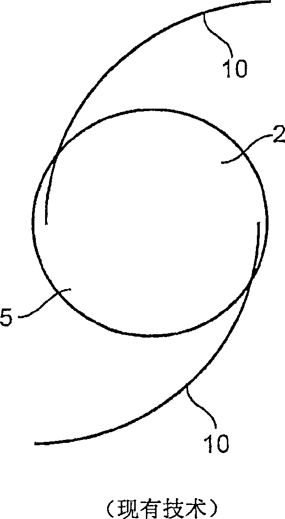
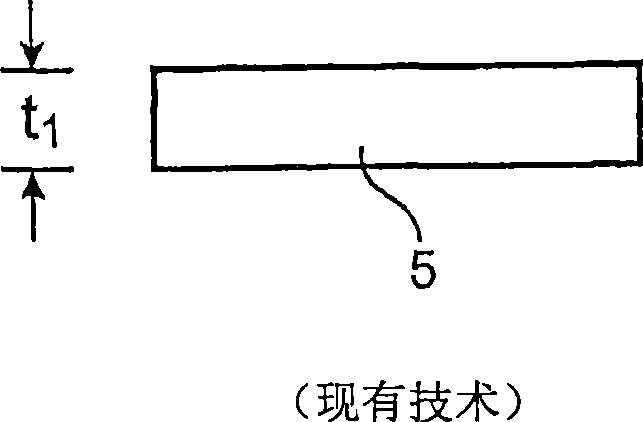
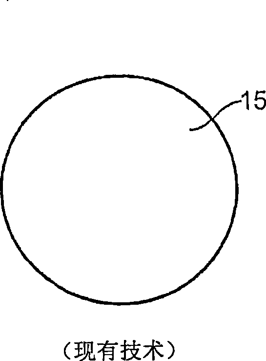
[0031] Figure 1A A top view of a cataract surgery lens implant 2 is shown. The circular optic 5 of the implant 2 has support feet 10 extending from the periphery of the optic. Support feet 10 are used to assist in centering and securing the optic within the pouch. Figure 1B A side view of the cataract surgery lens implant optics 5 is shown. Note that the thickness t of the optics 5 1 Typically 1 mm or more, and substantially greater than the thickness of the human cornea of ​​0.5 to 0.6 mm. The thickness of the optic 5 makes it unsuitable for use as a corneal lens implant. Figure 1C A top view of the corneal implant 15 is shown. Note that there are no supporting feet on the corneal implant. Figure 1D A side view of the corneal implant 15 is shown. Note that the thickness t 2 Sufficiently less than the thickness of the lens implant 5 for cataract surgery. The thickness t of the corneal implant 15 2 Usually it will be less than the thickness of the human cornea.

...


PUM


Abstract

A system comprising a hollow member is used to deliver a constrained corneal implant into a corneal pocket. The hollow member may be tapered and the system may further include an implant deformation chamber and an axial pusher to advance the implant through the hollow member.

Description

technical field [0001] Many different types of corneal implants have been developed to treat refractive errors and diseases. Because of limitations in the method of creating the corneal pocket, these implants are designed to be placed in the cornea by creating a corneal incision that is similar in size to or larger than the smallest dimension of the implant. Recently, two corneal pocket creation methods have been invented that allow the creation of a pocket with an external opening width that is less than the maximum internal width of the pocket. Both of these methods are capsular pocket creation by femtosecond lasers, with a particular focus on corneal ablation, as described in US 2004 / 0243159 and 0243160 by the inventors hereof, the entire disclosures of which are incorporated herein by reference . [0002] It is advantageous that a biocompatible corneal implant can be placed through an external incision which is smaller than the width of the implant, and it is especially ...

Claims


Application Information

Patent Timeline
Patent Type & Authority Applications(China)
IPC IPC(8): A61F2/14A61F2/02A61F2/16
CPCA61F2/145A61F2/146A61F2/143A61F2/142A61F2210/0019A61F2/148A61F2002/16965
Inventor 伊齐耶·舒埃
Owner 伊齐耶·舒埃
Why Eureka
Try Eureka