
Maintenance of an offshore wind farm making use of an assembly of a floating harbour ship and a plurality of shuttle vessels

a technology of shuttle vessels and wind farms, which is applied in the direction of anchoring arrangements, vessel safety, marine vessel transportation, etc., can solve the problems of inability to yield a profitable return on investment, the wind farm no longer being able to maintain the offshore wind turbine, and the disadvantage of large distances, etc., to achieve safe, efficient and reliable

Inactive Publication Date: 2013-01-31
Z KNOWLEDGE
View PDF4 Cites 14 Cited by
  • Summary
  • Abstract
  • Description
  • Claims
  • Application Information

AI Technical Summary

Benefits of technology

The invention aims to provide a safer, efficient, and reliable method for maintaining offshore wind farms, especially those located far out at sea.

Problems solved by technology

It has appeared that a rather intense maintenance of the offshore wind turbines is necessary.
Otherwise one or more of the turbines are likely to get broke, which results in the wind farm no longer being able to yield a profitable return on investment.
Such large distances are disadvantageous for the presently known maintenance methods that are presently used with wind farms lying much closer to the shore.
Also the risk of bad weather has a negative impact.
Thus the more frequent it is going to occur that sailing out with the shuttle vessels towards the wind farm is deemed to be too risky and that maintenance is not possible during that period.
This has an immediate negative effect on the total efficiency of the wind farm.
This however is rather hazardous and also very expensive for large scaled wind farms lying relative far off of the coast.
At this moment no methods are known for performing maintenance of large scaled wind farms lying relative far off of the coast in a cost effective manner.

Method used


Image

  • Maintenance of an offshore wind farm making use of an assembly of a floating harbour ship and a plurality of shuttle vessels
  • Maintenance of an offshore wind farm making use of an assembly of a floating harbour ship and a plurality of shuttle vessels
  • Maintenance of an offshore wind farm making use of an assembly of a floating harbour ship and a plurality of shuttle vessels

Examples


Embodiment Construction

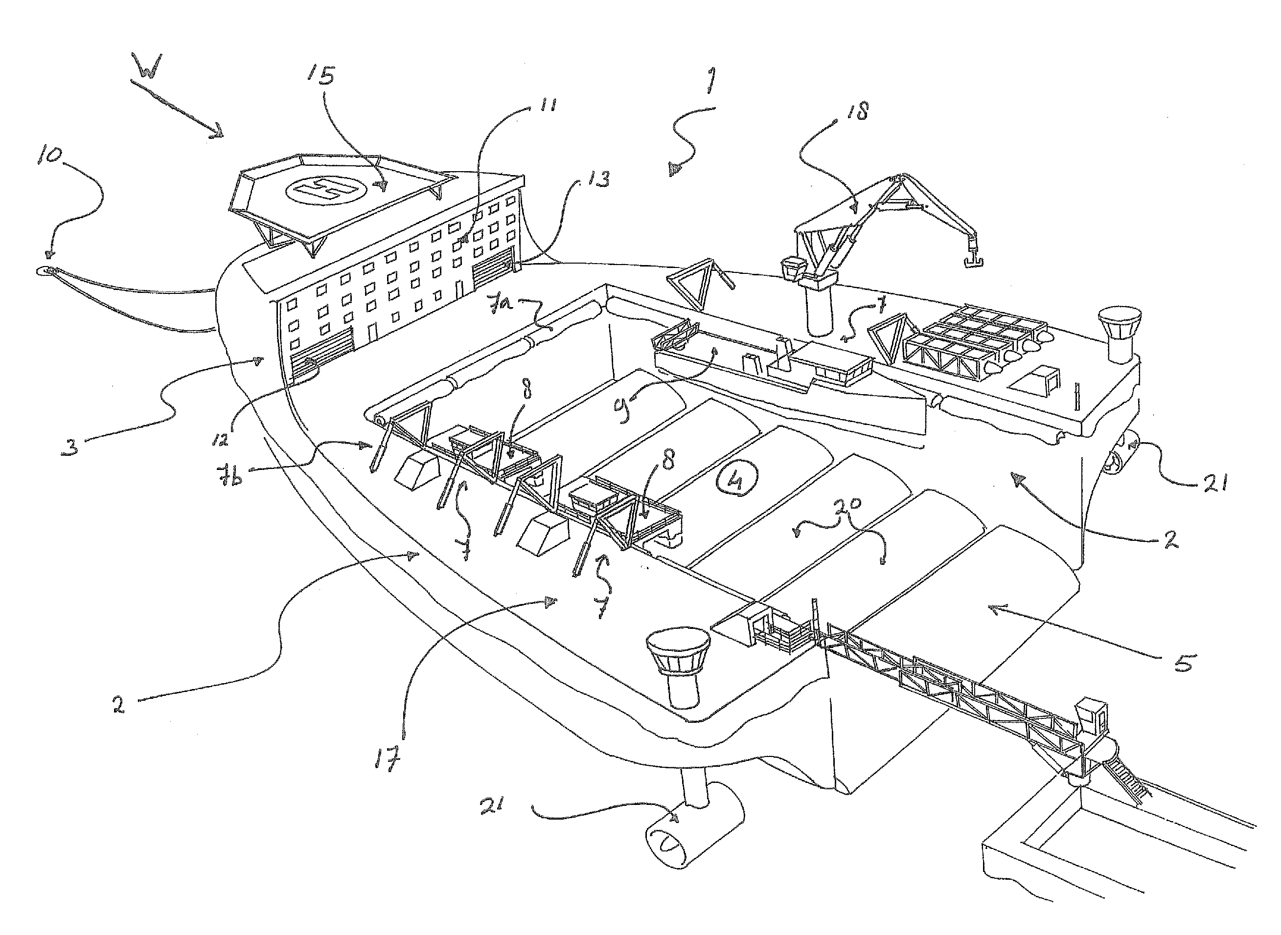
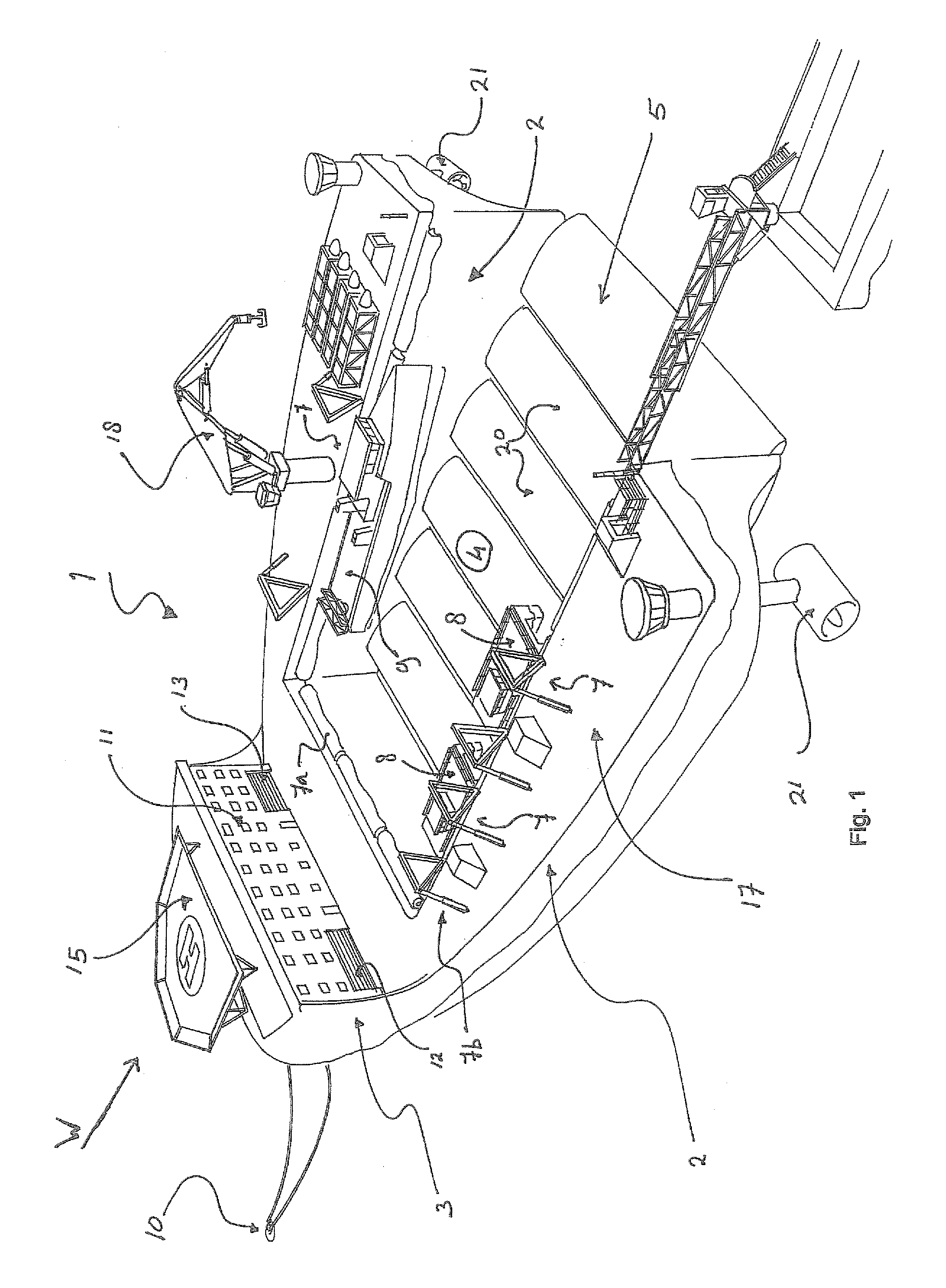
[0029]In FIG. 1 the harbour ship is indicated with the reference numeral 1. The ship 1 comprises a seaworthy floating construction with two longitudinal floating bodies 2 connected at their front sides by a bow 3. The floating bodies 2 and the bow 3 delimit respective sides of a water basin 4 spared out within the outlines of the floating construction. The basin 4 has an entrance opening 5 at the back side of the ship 1. The basin 4 is provided with mooring positions 7 alongside which fenders 7a and davits 7b are provided. At these mooring positions 7 shuttle vessels 8, 9 are moored. The shuttle vessels 8, 9 are substantially smaller than the ship 1 and the basin 4 comprises more than enough space for each of them to sail into and out of the basin 4 without bumping against each other.

[0030]The ship 1 is firmly anchored to the bottom of the sea by means of anchoring means 10. The bow 3 is provided with sleeping quarters 11 for approximately 50 to 150 man, and workplaces and storage r...


PUM


Abstract

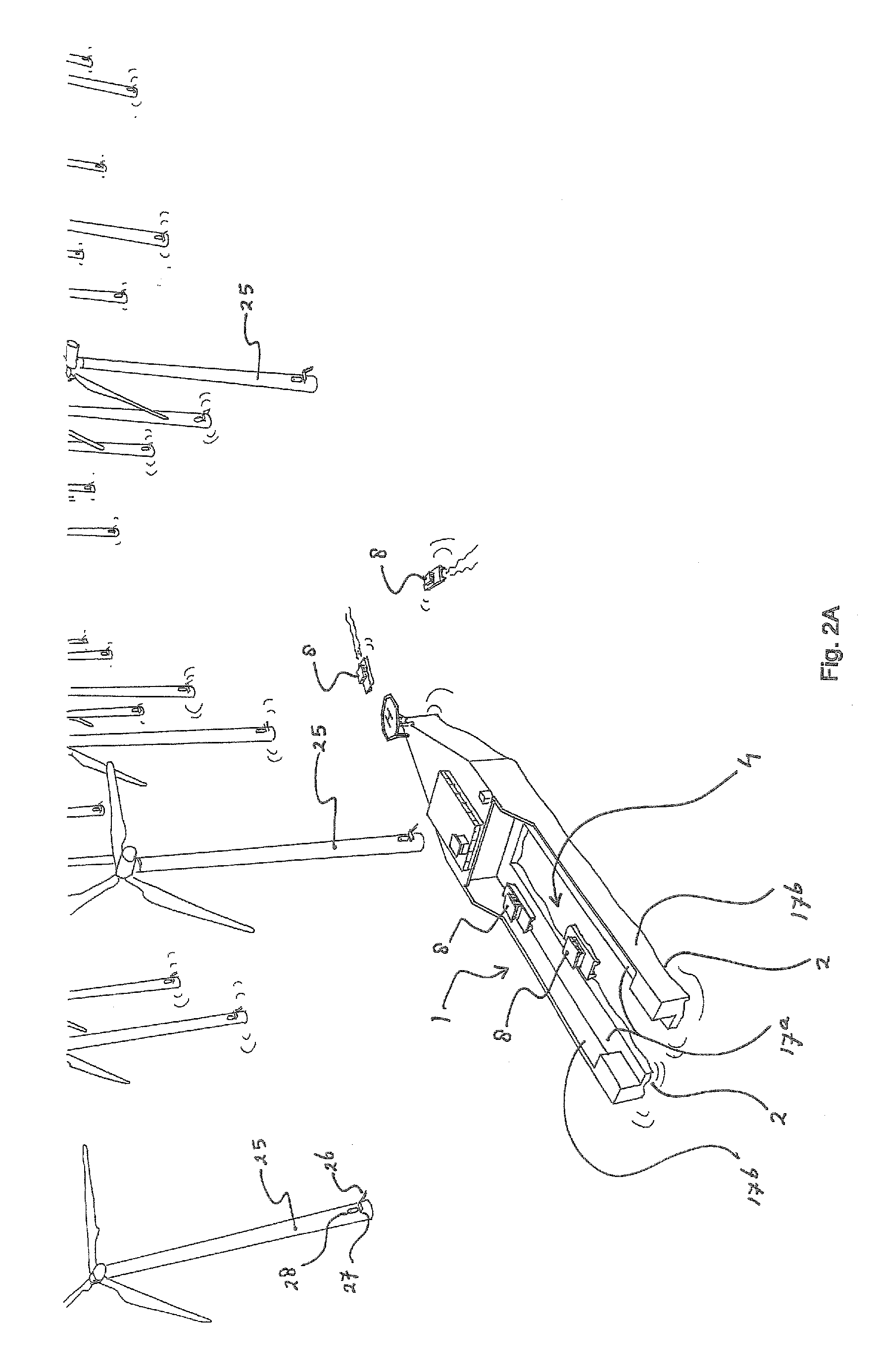
A method for use with maintenance of an offshore wind farm includes a plurality of offshore wind turbines installed in open sea, where the method uses an assembly of a plurality of shuttle vessels 8, 9 and a seaworthy harbour ship 1 which includes an internal harbour basin 4 within outlines of the ship 1 and a plurality of mooring positions 7 for mooring the plurality of shuttle vessels 8, 9 to the ship 1 when lying inside the basin 4, where the method further includes comprises sailing the assembly of the plurality of shuttle vessels 8, 9 and the harbour ship 1 towards an anchoring position near or in the wind farm and anchoring the harbour ship 1 there, and sailing the plurality of shuttle vessels 8, 9 back and forth between the mooring positions 7 of the anchored harbour ship 1 and distinctive ones of the wind turbines for performing the maintenance thereto.

Description

CROSS-REFERENCE TO RELATED APPLICATIONS[0001]This application is the National Stage of International Application No. PCT / NL2011 / 050052, filed Jan. 27, 2011, which claims the benefit of Netherlands Application No. 2004166, filed Jan. 28, 2010, the contents of which is incorporated by reference herein.FIELD OF THE INVENTION[0002]The invention relates to a method for use with the performance of maintenance to an offshore wind farm. The invention also relates to a harbour facility, in particular for use with such a method of performing maintenance to an offshore wind farm, and to an assembly of such a harbour facility and a plurality of shuttle vessels for transfer of service engineers from the harbour facility towards wind turbines of the farm and vice versa.BACKGROUND OF THE INVENTION[0003]An offshore wind farm usually comprises a cluster of some hundreds wind turbines. The large number is necessary to be able to efficiently transfer the generated electricity from the farm to the shor...

Claims


Application Information

Patent Timeline
Patent Type & Authority Applications(United States)
IPC IPC(8): B63B35/40B63B43/06B63B21/50B63B29/02B63B25/28B63H25/42
CPCB63B25/006Y02E10/727B63B35/086B63B35/00
Inventor PRINS, REINOUT KLAAR NORFOLC JAAP
Owner Z KNOWLEDGE
Learn More