Liquefaction method and system

a liquefaction method and system technology, applied in the field of liquefaction methods and systems, can solve the problems of improving efficiency, reducing the flexibility of closed-loop systems, and reducing the efficiency of liquefaction, so as to achieve the effect of safe, efficient and reliabl

Active Publication Date: 2013-06-18
AIR PROD & CHEM INC
View PDF39 Cites 18 Cited by
  • Summary
  • Abstract
  • Description
  • Claims
  • Application Information

AI Technical Summary

Benefits of technology

[0004]Embodiments of the present invention satisfy this need in the art by providing a safe, efficient, and reliable system and process for liquefaction, and specifically for natural gas liquefaction.

Problems solved by technology

The previous methods and systems for liquefaction, however, are problematic for several reasons.
For example, using simple compression systems and simple heat exchangers fails to result in improved efficiencies.
Moreover, the cost savings in using an open-loop system does not outweigh the flexibility of using a closed-loop system.

Method used


Image

  • Liquefaction method and system
  • Liquefaction method and system
  • Liquefaction method and system

Examples


example

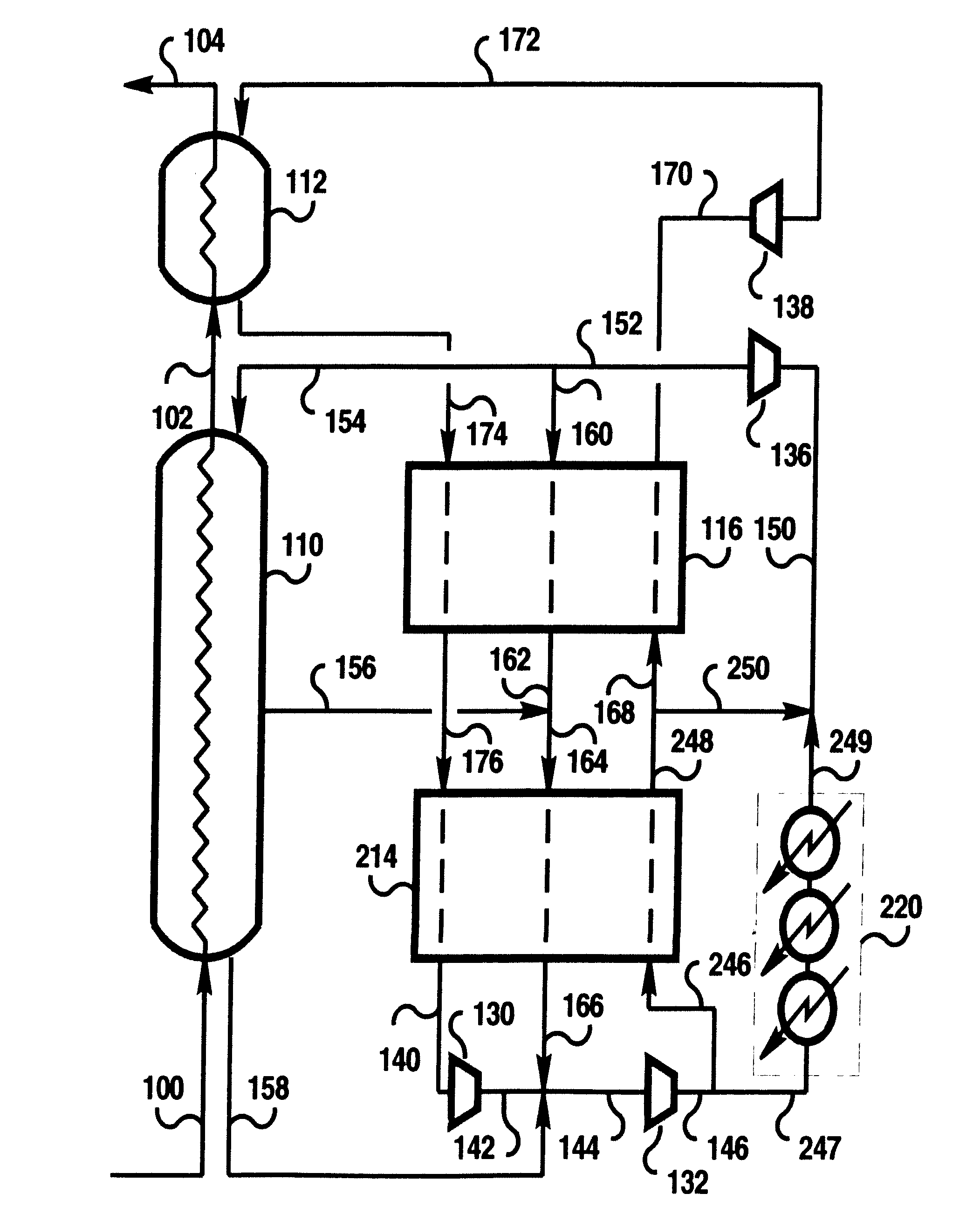
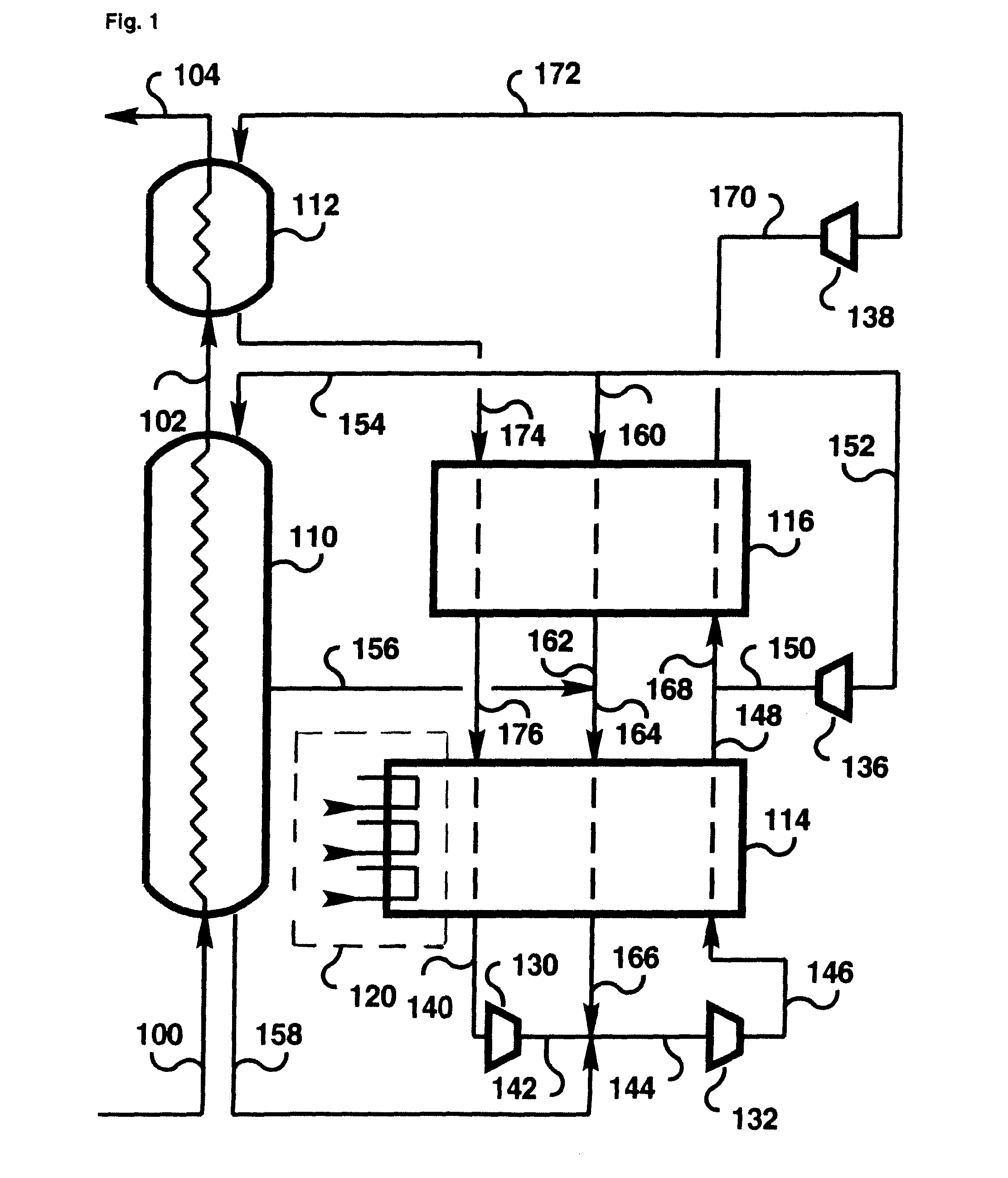
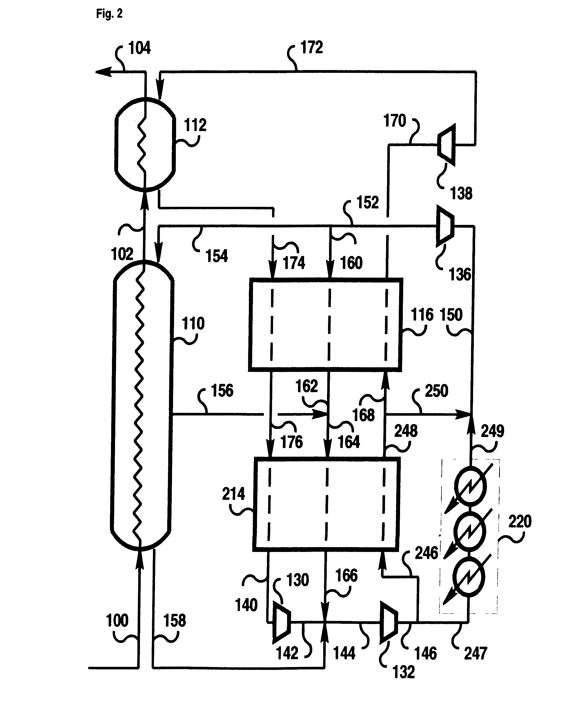
[0065]Referring to FIG. 3, 3,160 lbmol / hr of natural gas containing approximately 92% of methane, 1.6% of nitrogen, 3.4% of ethane, 2% of propane, and 1% of heavier components at 113° F. and 180 psia (stream 100) was precooled to approximately −31.6° F. by the refrigeration system 320 comprising 3 kettles with vaporization of R134A refrigerant (C2H2F4). The refrigerant was compressed in a 3-stage compressor, as illustrated in FIG. 6. The refrigerant compressor's suction pressure was approximately 0.5 bar absolute. Keeping the suction pressure at vacuum allowed subcooling to a lower temperature. Using a non-flammable refrigerant assured safe operation.

[0066]Resulting stream 301 was cooled in the liquefier heat exchanger 310 to −136° F. at which point the stream 102 was all liquid. It was then subcooled in the subcooler exchanger 112 to −261° F. providing resulting stream 104.

[0067]Gaseous nitrogen from the discharge of high-pressure refrigerant compressor 132 was at 104° F. and 1,200...


PUM


Abstract

A method for liquefaction using a closed loop refrigeration system, the method comprising the steps of (a) compressing a gaseous refrigerant stream in at least one compressor; (b) cooling the compressed gaseous refrigerant stream in a first heat exchanger; (c) expanding at least a first portion of the cooled, compressed gaseous refrigerant stream from the first heat exchanger in a first expander to provide a first expanded gaseous refrigerant stream; and (d) cooling and substantially liquefying a feed gas stream to form a substantially liquefied feed gas stream in a second heat exchanger through indirect heat exchange against at least a first portion of the first expanded gaseous refrigerant stream from the first expander, wherein the first expanded gaseous refrigerant stream exiting the first expander is substantially vapor.

Description

BACKGROUND[0001]Liquefaction methods and systems where refrigeration is generated by expanding gaseous refrigerant in a reverse-Brayton cycle are known. These methods and systems typically employ two expanders where the gaseous refrigerant is expanded to substantially the same pressure within tolerance of the pressure drop through equipment. Some systems also include more than two expanders with the cold expander discharge pressure being higher than the discharge pressures of the remaining expanders. These methods and systems have potentially simple compression systems because there are no streams introduced between compression stages, and simple heat exchangers because there are less passages and headers. Further some methods and systems use an open-loop system that utilizes the liquefied fluid as a refrigerant.[0002]The previous methods and systems for liquefaction, however, are problematic for several reasons. For example, using simple compression systems and simple heat exchange...

Claims


Application Information

Patent Timeline
Patent Type & Authority Patents(United States)
IPC IPC(8): F25J5/00
CPCF25J1/0022F25J1/005F25J1/0052F25J1/0072F25J1/0087F25J1/009F25J1/0095F25J1/0097F25J1/0204F25J1/0205F25J1/0254F25J1/0263F25J1/0265F25J1/0267F25J1/0268F25J1/0283F25J1/0284F25J1/0288F25J1/0294F25J1/004F25J2290/62F25J2220/62F25J2230/08F25J2230/32F25J2270/16F25J1/0292F25J1/02F25J1/00F25J5/00
Inventor ROBERTS, MARK JULIANBROSTOW, ADAM ADRIAN
Owner AIR PROD & CHEM INC
Why Eureka
Try Eureka