Alternate fuel storage system and method

a technology of alternative fuel and storage system, which is applied in the direction of liquid fuel feeder, combustion air/fuel air treatment, machines/engines, etc., can solve the problems of multiple performance and efficiency limitations of methods, affecting the efficiency of alternative fuel storage, and increasing viscosity of alternative fuel

Active Publication Date: 2013-01-31
GILBARCO
View PDF10 Cites 0 Cited by
  • Summary
  • Abstract
  • Description
  • Claims
  • Application Information

AI Technical Summary

Benefits of technology

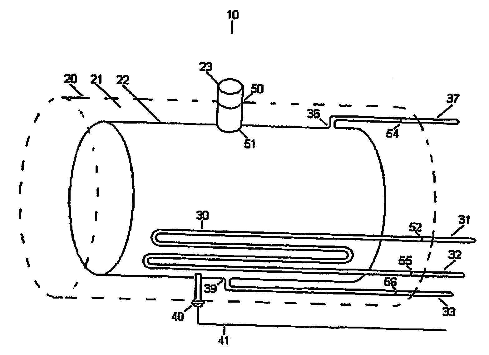
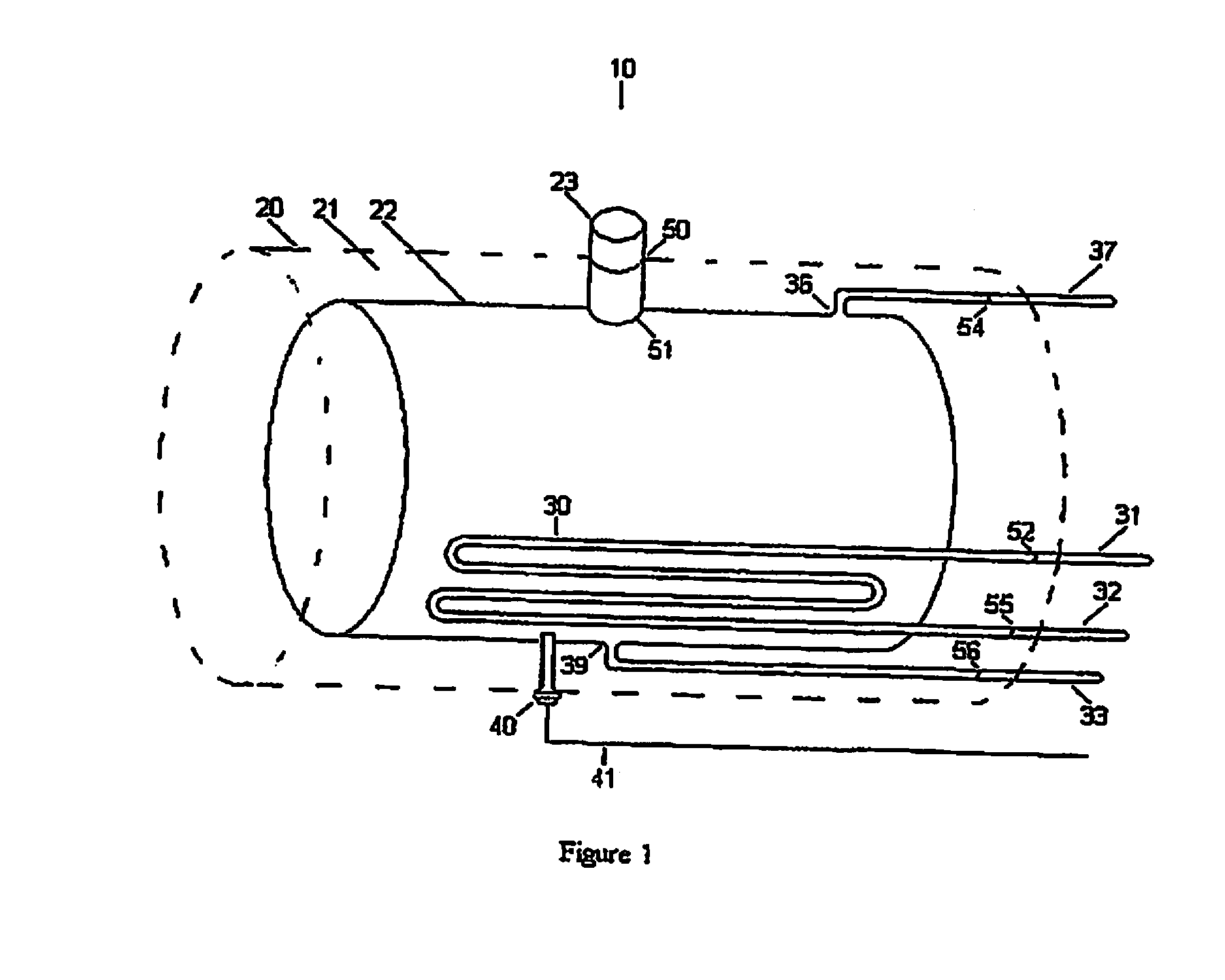
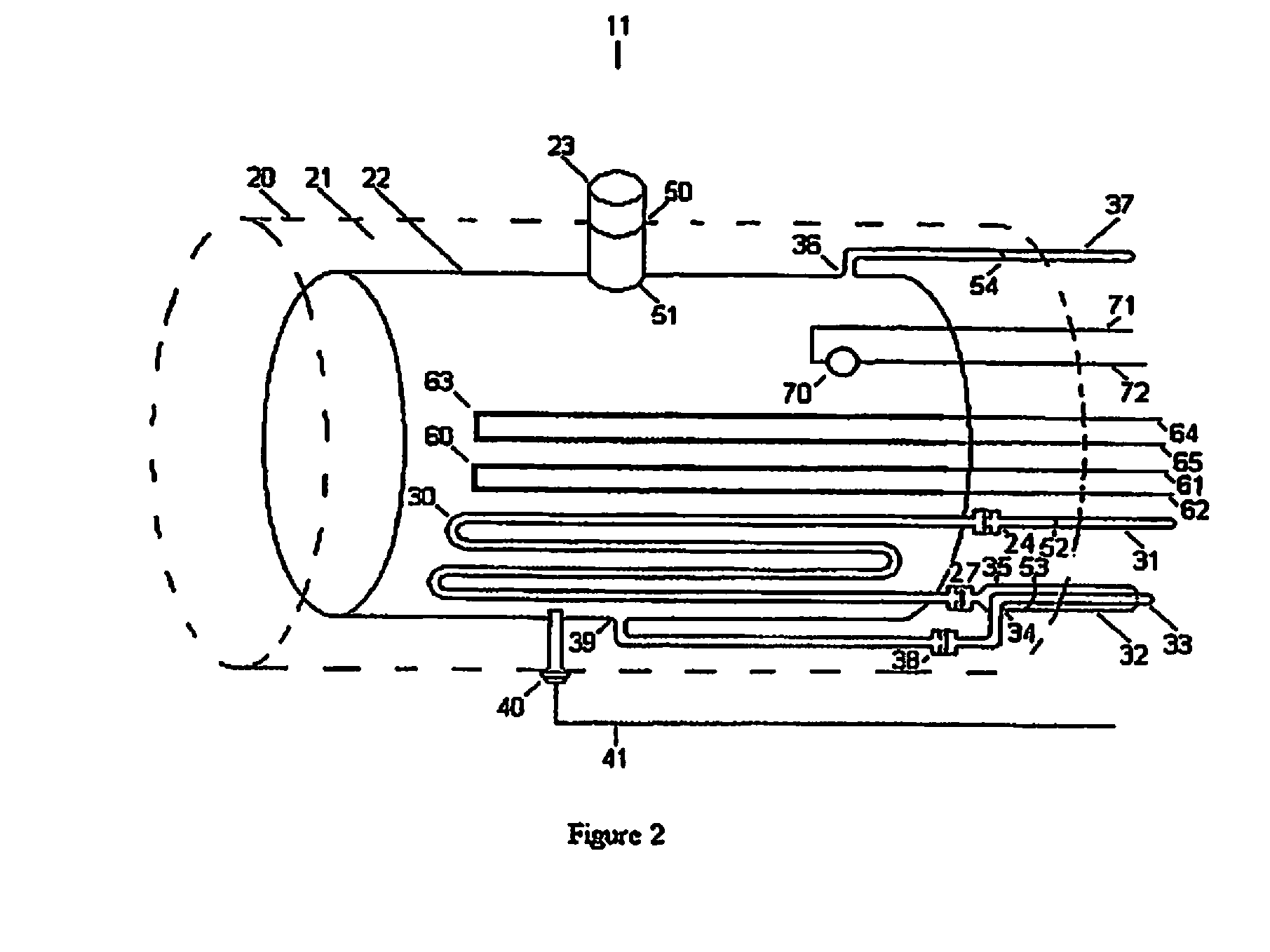
This patent is about a fuel tank for storing alternative fuels and supplying them to an engine. The tank has an inner shell that holds the fuel, an outer shell that creates space between them, and a heating unit that adds heat to the fuel. In some cases, the space between the inner and outer shells is filled with gas, and in others, it is insulated. The tank can also have sensors to monitor the fuel level, viscosity, and temperature. The technical effects of this invention are to provide a more efficient and flexible way to store and heat fuel for use in an engine, which can improve engine performance and fuel efficiency.

Problems solved by technology

Likewise, if left in a storage tank to cool, the alternate fuel has a tendency to increase in viscosity, congeal or solidify within fuel storage components.
As a result, these systems typically exhibit a delay required to heat the alternate fuel and must run on diesel fuel until the alternate fuel is at a usable viscosity, effectively forfeiting utilization of the alternate fuel while consuming diesel.
While functional, this method suffers multiple performance and efficiency limitations.
This has the effect of rapidly promoting congealment and solidification of the alternate fuel if the engine is turned off, thereby requiring a reheat cycle and corresponding delay upon the vehicle's next use, and again the consumption of diesel fuel during this period.
Also, with heat energy being continuously lost, the efficiency of the heating process itself is reduced; thus, the time required to heat is increased.
In colder climates, the effect of heat energy loss worsens, heating delay increases, and the consumption of diesel fuel likewise increases.
Similarly, weather phenomena such as snow or rain, or water splash upon the storage vessel, can result in heat energy loss, potentially to such degree as to overcome the heat energy provided by the diverted engine coolant, thus yielding a net decrease in alternate fuel temperature and the risk of congealment or solidification of the alternate fuel while in use.
Another performance and efficiency limitation occurs if the initial temperature of the engine coolant is lower than the initial temperature of the alternate fuel.
The First Law of Thermodynamics dictates that any heat energy removed must again be replaced just to regain the initial alternate fuel temperature prior to cold engine start, thus heating delay is further increased and the consumption of diesel fuel likewise increased.
Yet another limitation arises from the heat energy source used to control alternate fuel viscosity being the engine coolant itself, which results in the system being dependent upon running the engine on diesel or primary fuel for a period of time sufficient to heat the engine coolant before the alternate fuel becomes usable and available to the engine.

Method used


Image

  • Alternate fuel storage system and method
  • Alternate fuel storage system and method
  • Alternate fuel storage system and method

Examples


Embodiment Construction

[0020]The present inventions now will be described more fully hereinafter with reference to the accompanying drawings, in which some, but not all embodiments of the inventions are shown. Indeed, these inventions may be embodied in many different forms and should not be construed as limited to the embodiments set forth herein; rather, these embodiments are provided so that this disclosure will satisfy applicable legal requirements. Like numbers refer to like elements throughout.

[0021]Unless otherwise defined, all terms (including technical and scientific terms) used herein have the same meaning as commonly understood by one of ordinary skill in the art to which this invention belongs. It will be further understood that terms, such as those defined in commonly used dictionaries, should be interpreted as having a meaning that is consistent with their meaning in the context of the relevant art and will not be interpreted in an idealized or overly formal sense unless expressly so defined...


PUM


Abstract

A fuel tank for storing an alternate fuel and providing the fuel to an internal combustion engine includes: an inner shell with an internal cavity designed to store fuel; an outer shell configured and positioned relative to the inner shell such that an interstitial volume is created between the inner and outer shells; and a heating unit positioned in the interstitial volume. In some embodiments, the interstitial volume is filled with air; in other embodiments, the interstitial volume is filled with a thermally insulative material.

Description

PRIORITY APPLICATION[0001]The present application is a continuation application of U.S. patent application Ser. No. 11 / 748,022, entitled “ALTERNATE FUEL STORAGE SYSTEM AND METHOD” and filed on May 14, 2007, which claims priority to U.S. Provisional Patent Application Ser. No. 60 / 747,811, filed on May 21, 2006, both of which are incorporated herein by reference in their entireties.FIELD OF THE INVENTION[0002]The present invention relates to fuel systems for internal combustion engines and more particularly to fuel systems that provide an alternate fuel to an internal combustion engine.BACKGROUND OF THE INVENTION[0003]For a variety of reasons, most of which relate to environmental and alternative energy pursuits, certain primary fuel engines, such as diesel engines, can be made to accommodate alternate fuels, such as straight vegetable oil (SVO), “biodiesel,” and other fuel oils (hereinafter “alternate fuels”). However, practical applications have demonstrated that alternate fuel shou...

Claims


Application Information

Patent Timeline
Patent Type & Authority Applications(United States)
IPC IPC(8): F02M31/02
CPCF02M31/10Y02T10/126F02M37/0064F02M31/125Y02T10/12
Inventor PAYNE, EDWARDWILLIAMS, RODGER
Owner GILBARCO
Why Eureka
Try Eureka