
System and method for controlling and monitoring a drilling operation using refined solutions from a panistic inversion

a technology of panistic inversion and control solution, which is applied in the direction of survey, directional drilling, borehole/well accessories, etc., can solve the problems of inability to accurately control the drilling operation, the sensitivity of the measurement to some of the parameters of a particular earth model may be limited, and the model is too simplified

Active Publication Date: 2013-01-31
SCHLUMBERGER TECH CORP
View PDF3 Cites 24 Cited by
  • Summary
  • Abstract
  • Description
  • Claims
  • Application Information

AI Technical Summary

Benefits of technology

The patent describes a method and system for monitoring and controlling a drilling operation. It involves using parameters to define a probability risk threshold for the drilling operation. These parameters may include default values or job-specific values determined during the drilling operation. The method may also include using a panistic inversion and risk estimate module to receive measured data from the drilling operation and generate a plurality of mathematical solutions. These solutions may be refined to produce statistics for the parameters selected for the drilling operation. If the probability risk exceeds a given threshold associated with the drilling operation, an alert may be generated, which may be audible or visual.

Problems solved by technology

Furthermore, the sensitivity of the measurements to some of the parameters of a particular earth model may be limited when such conventional inversions are used.
Simplifications of the earth model can result in models that are too simplified.
The reliance of these simplified models may result in a less than optimal geo-steering decision.
Putting these single solutions aside, one of ordinary skill in the art recognizes that drilling a well is a complex operation that requires a lot of decisions to be made and risks to be managed.
On the other hand, drilling into a high-pressure zone because drilling is occurring too quickly and without considering risks for the path the of the drilling system may result in catastrophic losses.

Method used


Image

  • System and method for controlling and monitoring a drilling operation using refined solutions from a panistic inversion
  • System and method for controlling and monitoring a drilling operation using refined solutions from a panistic inversion
  • System and method for controlling and monitoring a drilling operation using refined solutions from a panistic inversion

Examples


Embodiment Construction

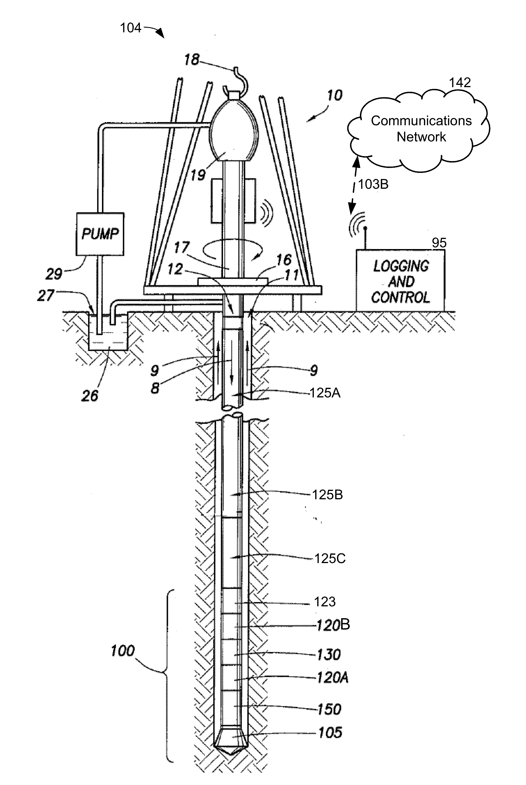
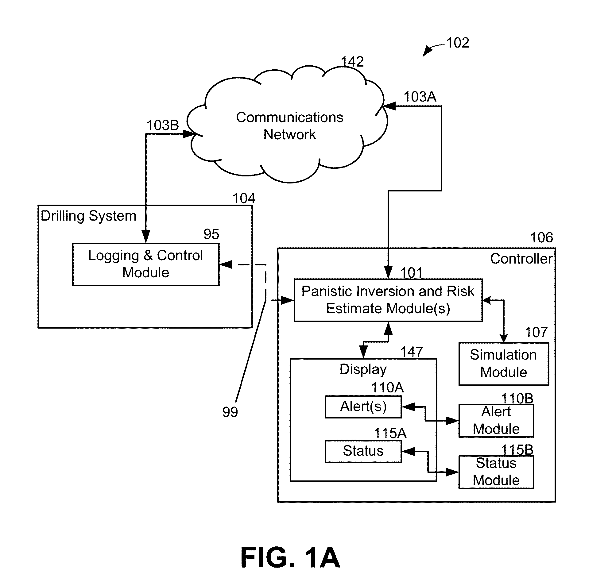
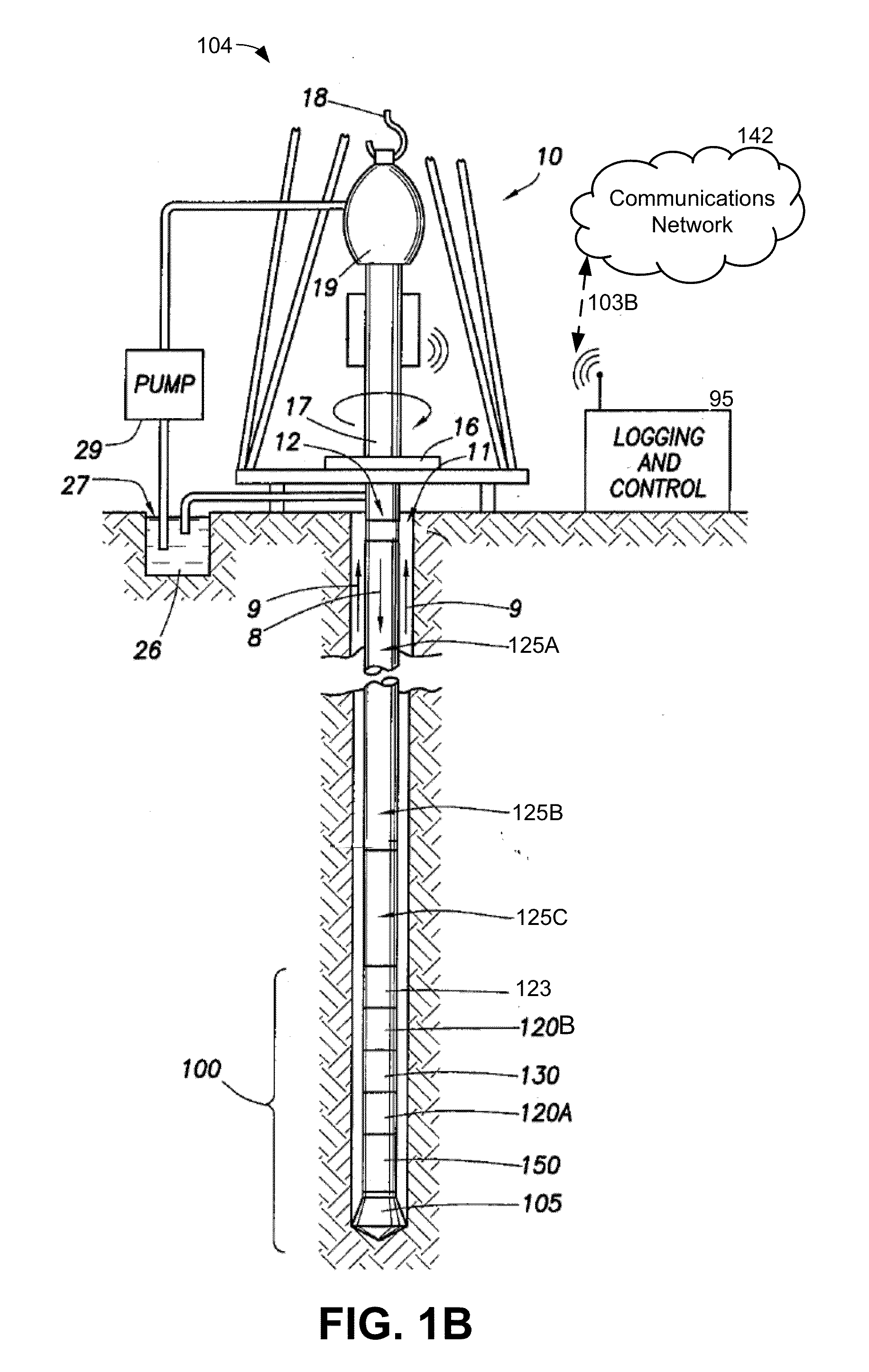
[0021]Referring initially to FIG. 1A, this figure is a diagram of a system 102 for controlling and monitoring a drilling operation using refined solutions from a panistic inversion. The system 102 comprises a panistic inversion and risk estimate module 101 and a simulation module 107 forming part of a controller 106. The system 102 also includes a drilling system 104 which has a logging and control module 95. The controller 106 further comprises a display 147 for conveying alerts 110A and status information 115A that are produced by an alerts module 110B and a status module 115B. The controller 102 may communicate with the drilling system 104 via a communications network 142.

[0022]The controller 102 and the drilling system 104 may be coupled to the communications network 142 via communication links 103. Many of the system elements illustrated in FIG. 1A are coupled via communications links 103 to the communications network 142.

[0023]The links 103 illustrated in FIG. 1A may comprise ...


PUM


Abstract

During a drilling operation, measured data from the drilling operation may be received with a panistic inversion and risk estimate module. The panistic inversion and risk estimate module may generate a plurality of mathematical solutions from a panistic inversion that uses the measured data and one or more earth models. The one or more earth models having various parameters may be selected prior to drilling and / or while the drilling operation occurs. For each solution of the plurality of mathematical solutions generated from the panistic inversion, the panistic inversion and risk estimate module may determine if the measured data exceeds one or more probability risk thresholds associated with the drilling operation. If the measured data exceeds the probability risk threshold associated with the drilling operation, then the panistic inversion and risk estimate module may generate an alert.

Description

DESCRIPTION OF THE RELATED ART[0001]Forward-model-based inversion techniques have been used for many years to help interpret downhole log measurements of drilling operations. Prior to and during drilling operations, earth formations may be represented by one or more earth models, with each earth model having a series of layers with different properties and a corresponding parameters. Forward modeling is typically used to compute the expected response of a particular earth model, which can be compared to the actual measurements taken during a drilling operation. As understood by one of ordinary skill in the art, inversions may allow one to determine the parameters of an earth model, such as the number(s) and position(s) of earth layer boundaries, as well as values of the properties in each earth layer.[0002]The number of parameters needed to accurately describe formations in earth layers is often larger than the number of independent measurements available. For the measurements that ...

Claims


Application Information

Patent Timeline
IPC IPC(8): E21B47/00E21B7/04G01V3/00G01V9/00G06F19/00
CPCG06Q50/02E21B44/00E21B47/022
Inventor HELIOT, DENISCRARY, STEVEN F.SEYDOUX, JEAN
Owner SCHLUMBERGER TECH CORP
Learn More