Wave equation illumination

a wave equation and wave equation technology, applied in the field of seismic data processing, can solve the problem that the ray-tracing method is typically computationally efficien

Active Publication Date: 2011-07-21
WESTERNGECO LLC
View PDF2 Cites 28 Cited by
  • Summary
  • Abstract
  • Description
  • Claims
  • Application Information

AI Technical Summary

Benefits of technology

[0009]Described herein are implementations of various technologies for creating an illumination map using wave equations. In one implementation, a method for creating an illumination map using wave equations may include receiving an earth model that represents one or more properties of the earth. The method may then include receiving a target area in the earth model and propagating one or more wavefields from the target area to a potential seismic data acquisition region in the earth model. After propagating the wavefields, the method may include decomposing the propagated wavefields into one or more subsets of the propagated wavefields. The method may then include creating the illumination map based on the subsets of the propagated wavefields. In one implementation, the illumination map may indicate one or more contributions of one or more synthetic source and receiver pairs for illuminating the target area in the earth model. The method may then include creating a seismic survey design based on the illumination contributions.
[0010]In another implementation, a computer application may receive an earth model representing one or more properties of the earth, receive a target area in the earth model and propagate one or more wavefields from a potential seismic data acquisition region in the earth model to the target area. After propagating the wavefields from the potential seismic data acquisition region to the target area, the computer application may decompose the propagated wavefields into one or more subsets of the propagated wavefields. The computer application may then create an illumination map based on the subsets of the propagated wavefields, wherein the illumination map indicates one or more contributions of one or more synthetic source and receiver pairs for illuminating the target area in the earth model. After creating the illumination map, the computer application may create a seismic survey design based on the contributions.
[0011]The claimed subject matter is not limited to implementations that solve any or all of the noted disadvantages. Further, the summary section is provided to introduce a selection of concepts in a simplified form that are further described below in the detailed description section. The summary section is not intended to identify key features or essential features of the claimed subject matter, nor is it intended to be used to limit the scope of the claimed subject matter.

Problems solved by technology

The ray-tracing method is typically computationally efficient, but it may fail in areas where complex variations exist near the target area.

Method used


Image

  • Wave equation illumination
  • Wave equation illumination
  • Wave equation illumination

Examples


Embodiment Construction

[0019]The discussion below is directed to certain specific implementations. It is to be understood that the discussion below is only for the purpose of enabling a person with ordinary skill in the art to make and use any subject matter defined now or later by the patent “claims” found in any issued patent herein.

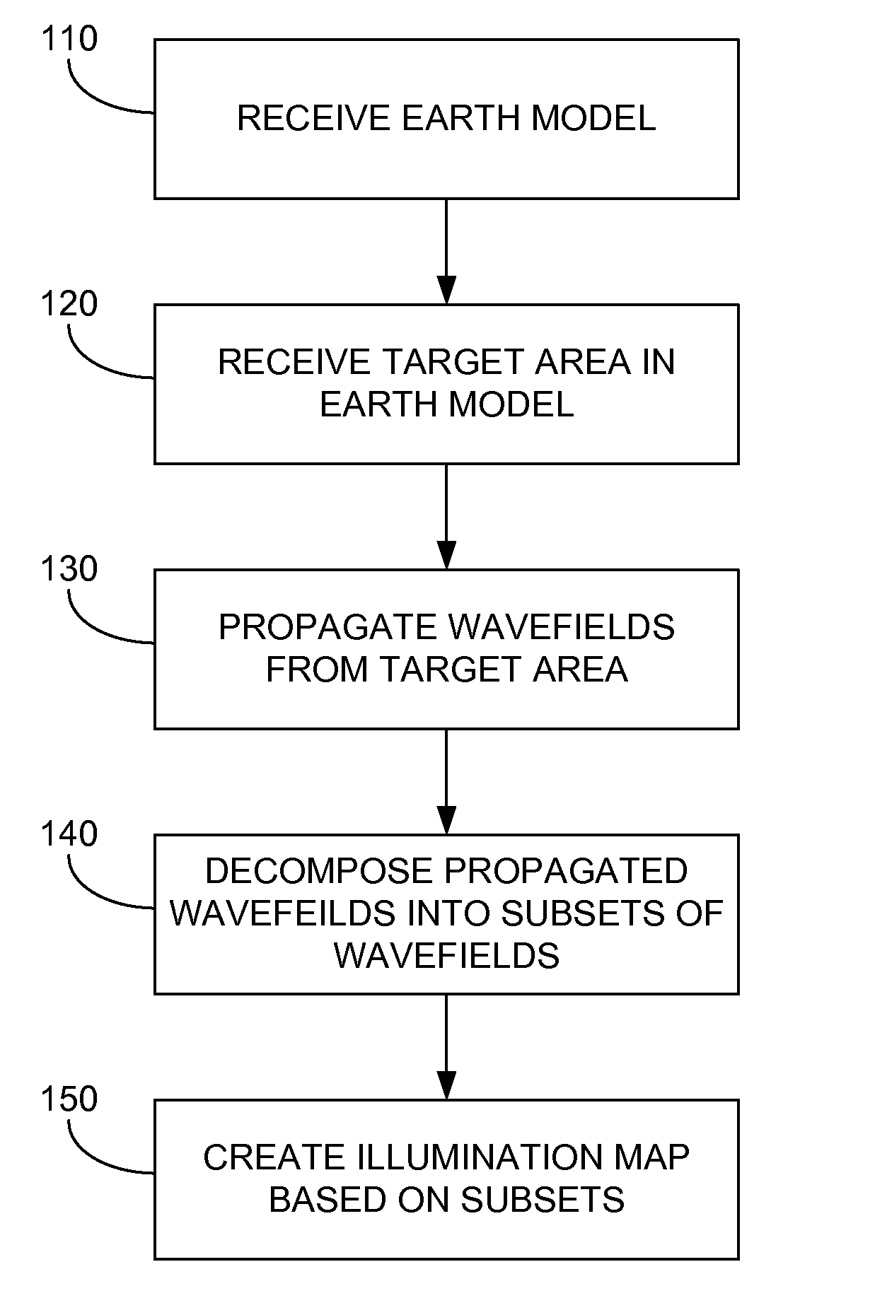
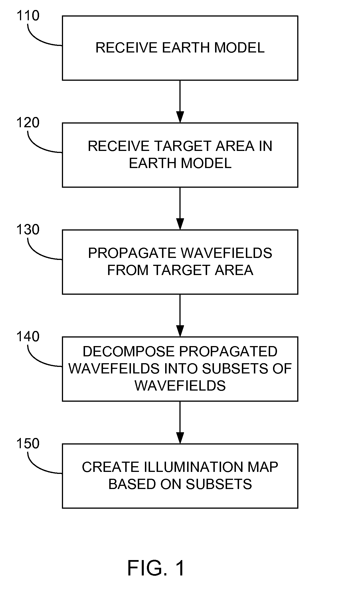
[0020]The following paragraphs provide a brief description of one or more implementations of various technologies and techniques directed at creating an illumination map using wave equations.

[0021]In one implementation, a method for creating an illumination map using wave equations may be performed by a computer application. Initially, the computer application may receive an earth model from a user. The earth model may represent various seismic properties of the earth. The computer application may then receive a target area from the user. The target area may indicate a general vicinity, a point, a horizon or a region in the subsurface of the earth that may be of interest to ...


PUM


Abstract

A method for generating an illumination map. The method includes receiving an earth model that represents one or more properties of the earth. The method then includes receiving a target area in the earth model and propagating one or more wavefields from the target area to a potential seismic data acquisition region in the earth model. After propagating the wavefields, the method includes decomposing the propagated wavefields into one or more subsets of the propagated wavefields and creating the illumination map based on the subsets of the propagated wavefields. The illumination map may indicate one or more contributions of one or more synthetic source and receiver pairs for illuminating the target area in the earth model. The method may then include creating a seismic survey design based on the contributions.

Description

BACKGROUND[0001]1. Field of the Invention[0002]Implementations of various technologies described herein generally relate to seismic data processing.[0003]2. Description of the Related Art[0004]The following descriptions and examples are not admitted to be prior art by virtue of their inclusion within this section.[0005]Seismic exploration is widely used to locate and / or survey subterranean geological formations for hydrocarbon deposits. Since many commercially valuable hydrocarbon deposits are located beneath areas of land and bodies of water, various types of land and marine seismic surveys have been developed.[0006]In a typical land or marine seismic survey, seismic sensors are installed in specific locations around an area of the earth in which hydrocarbon deposits may exist. Seismic sources, such as vibrators or air guns, may move across the area and produce acoustic signals, commonly referred to as “shots,” directed down to the earth, where they are reflected from the various s...

Claims


Application Information

Patent Timeline
Patent Type & Authority Applications(United States)
IPC IPC(8): G01V1/28
CPCG01V2210/67G01V1/282
Inventor LAPILLI, CINTIANICHOLS, DAVIDGONZALEZ, ALFONSO
Owner WESTERNGECO LLC
Why Eureka
Try Eureka