Real time earth model for collaborative geosteering

a geosteering and real-time earth technology, applied in the field of subsurface earth formation model formation, can solve problems such as inability to update or revise conventional techniques, inability to update data or well models, and insufficient data for revised or updated models. the effect of drilling efficiency

Active Publication Date: 2008-04-15
SAUDI ARABIAN OIL CO
View PDF17 Cites 33 Cited by
  • Summary
  • Abstract
  • Description
  • Claims
  • Application Information

AI Technical Summary

Benefits of technology

[0010]An earth model is formed in real time during drilling of a well by incorporating up-to-the-minute knowledge derived from geology, seismic, drilling, and engineering data. Logging-While-Drilling (LWD) or Measuring-While-Drilling (MWD) data are directly from the drilling rig as the well is drilled. The LWD or MWD data are sent to visualization centers and compared with other data such as existing geological models, the proposed well plan and present interpretation of the subsurface stratigraphy. When the real time data from the well indicates a different stratigraphy than the well model, revised models are formed based on the newly acquired well data. The present invention thus enables experts to analyze unexpected results and update the geological model within minutes of penetration of a formation during drilling. Well drilling efficiency is improved in real time, and an “on-the-spot” road map is provided to steer the drill bit based on the newly developed map for maximal reservoir contact and drilling accuracy.

Problems solved by technology

There are still, however, conceptual gaps in knowledge of the actual subsurface structure in well plans by geoscientists and engineers for a well to be drilled.
However, so far as is known, conventional techniques to form revised or updated models have taken days or weeks.
Thus, the revised data or well model was not available until long after drilling operations had passed the proper location for corrections to be made in steering of the drill bit to better locate the well in the reservoir of interest.

Method used


Image

  • Real time earth model for collaborative geosteering
  • Real time earth model for collaborative geosteering
  • Real time earth model for collaborative geosteering

Examples


Embodiment Construction

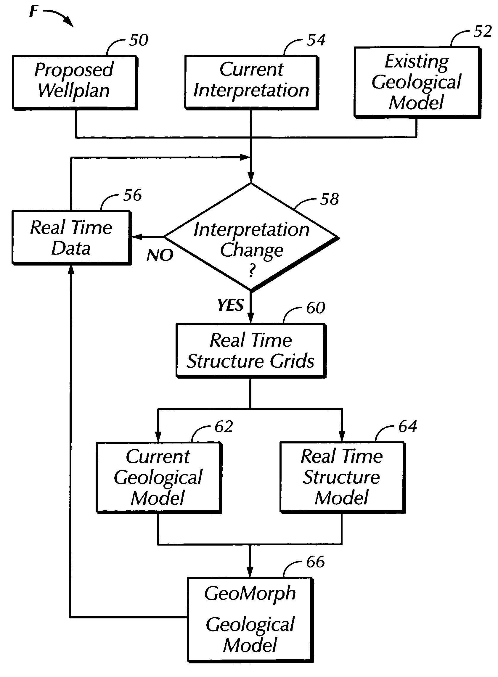
[0022]In the drawings, FIG. 1 illustrates an example of a prior art measurement-while-drilling (MWD) system S for gathering data about subsurface formations during drilling. The system S may be one of several commercially available types used during drilling operations at a wellsite to gather data. Once the data has been obtained, it is then available for processing in a manner to be set forth according to the present invention. The system S includes as a part of the drilling rig a downhole subassembly 10 that moves within a borehole 14 behind a drill bit 12 at a lower end of a drill string 16 during drilling of the borehole 14. As shown in FIG. 1, the drill bit 12 and the borehole 14 have transitioned from an initial vertical direction to a generally horizontal path into subsurface earth formations 18. The downhole subassembly 10 is preferably positioned as close as practical to the drill bit 12.

[0023]The drill bit 12 may be rotated in several ways during drilling operations. The d...


PUM


Abstract

An earth model is formed in real time during drilling of a well by incorporating up-to-the-minute knowledge derived from geology, seismic, drilling, and engineering data. The process of forming the model utilizes Logging-While-Drilling (LWD) or Measuring-While-Drilling (MWD) data directly from the drilling rig as the well is drilled. The LWD or MWD data is sent to visualization centers and compared with other data such as existing geological models, the proposed well plan and present interpretation of the subsurface stratigraphy. The results of the comparison enable experts to analyze anomalous results and update the geological model within minutes of penetration of a formation during drilling. Well drilling efficiency is improved, and an “on-the-spot” road map is provided for maximal reservoir contact and pinpoint accuracy.

Description

RELATED APPLICATIONS[0001]This Application claims the benefit of U.S. Provisional Patent Application Ser. No. 60 / 537,595 filed Jan. 20, 2004.BACKGROUND OF THE INVENTION[0002]1. Field of the Invention[0003]The invention herein relates to forming models of subsurface earth formations based on data obtained from wells being drilled in those formations.[0004]2. Description of the Related Art[0005]With increased competition in the energy market, oil companies face a daunting task of improving accuracy while reducing cycle time. Technologies in horizontal drilling, real time monitoring, and reservoir modeling have advanced significantly during the last few years. There are still, however, conceptual gaps in knowledge of the actual subsurface structure in well plans by geoscientists and engineers for a well to be drilled.[0006]Typically, the well plan is an earth model based on best available information from surveys, well logs and other reservoir techniques. The interest is to locate a we...

Claims


Application Information

Patent Timeline
Patent Type & Authority Patents(United States)
IPC IPC(8): G06G7/48E21B41/00E21B49/00
CPCE21B49/00E21B41/00E21B49/087
Inventor SUNG, ROGER R.LEWIS, KENNETH A.
Owner SAUDI ARABIAN OIL CO
Why Eureka
Try Eureka