
Automatic work light activation and deactivation

a technology of work light and work light, applied in the direction of digital transmission, transmission, modulated carrier system, etc., can solve the problem of affecting visibility and affecting visibility

Inactive Publication Date: 2013-01-31
DEERE & CO
View PDF6 Cites 0 Cited by
  • Summary
  • Abstract
  • Description
  • Claims
  • Application Information

AI Technical Summary

Benefits of technology

The invention is about lighting for a work vehicle. It can automatically turn on when needed and turn off when not needed. This is useful when the work area is too dark for observation or when there are too many reflections that could impair visibility. The technical effect is to improve the safety and efficiency of work operations.

Problems solved by technology

Such reflections may impair visibility when ambient lighting conditions, for example, nighttime conditions, provide insufficient lighting.

Method used


Image

  • Automatic work light activation and deactivation
  • Automatic work light activation and deactivation
  • Automatic work light activation and deactivation

Examples


Embodiment Construction

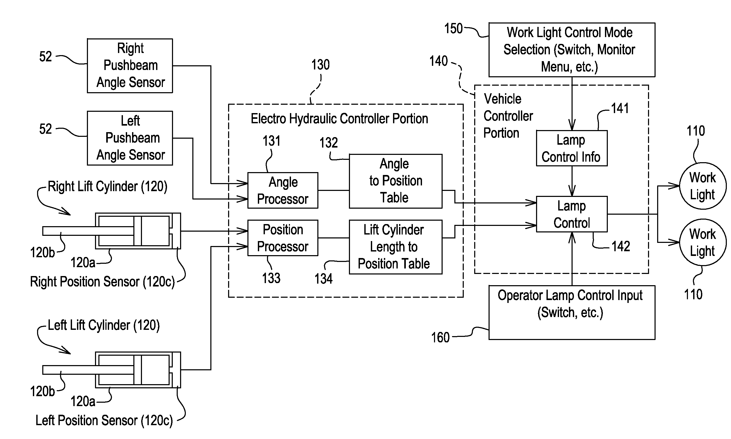
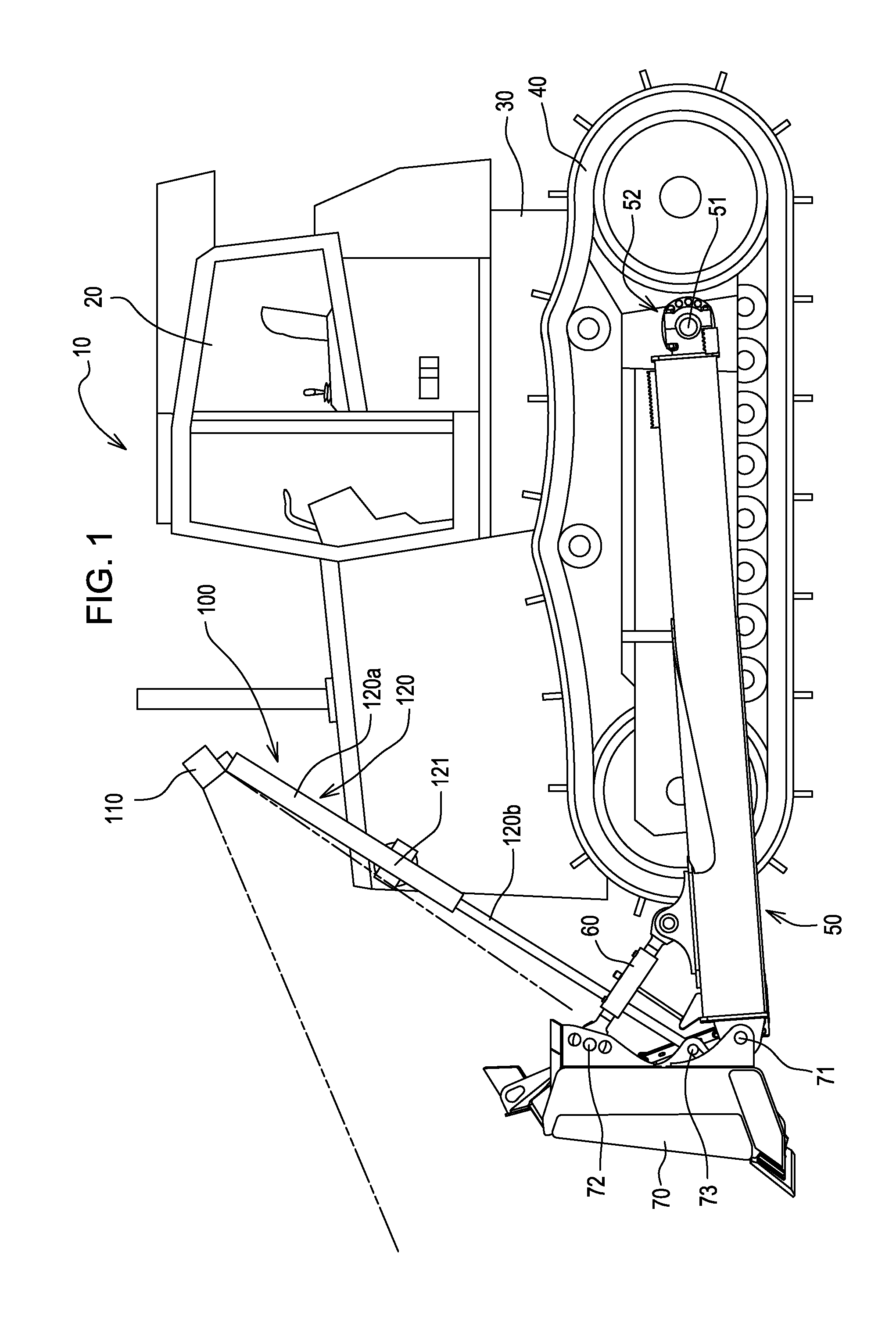
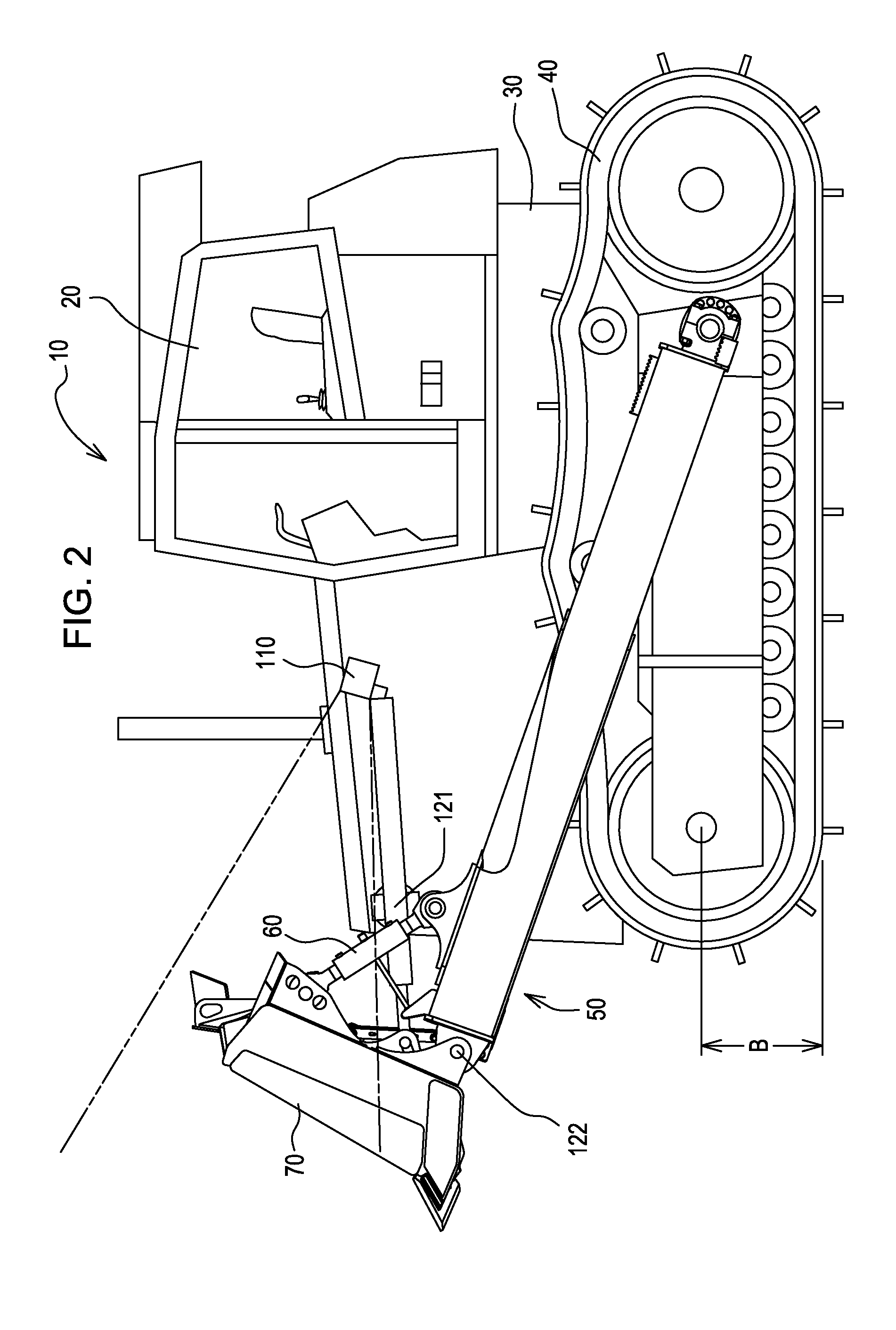
[0009]FIG. 1 illustrates an exemplary work vehicle, i.e., a dozer 10, including a cab 20, a frame 30 to which the cab 20 is attached, an undercarriage 40 attached to and supporting the frame 30, a pushbeam 50 pivotally attached to the undercarriage 40 at pushbeam pivot 51, a pitch cylinder 60 pivotally attached to the pushbeam 50 at pitch cylinder pivot 61, a blade 70 pivotally attached to the pushbeam 50 at first blade pivot 71 and the pitch cylinder 60 at second blade pivot 72, and a lift cylinder assembly 100 pivotally attached to the frame 30 at a lift cylinder pivot 121 and the blade 70 at third blade pivot 73.

[0010]As illustrated in FIG. 1, the lift cylinder assembly 100 may include: a work light 110; a hydraulic lift cylinder 120 including a hydraulic lift cylinder barrel 120a and a hydraulic lift cylinder rod 120b; and the hydraulic lift cylinder pivot 121 to which the hydraulic lift cylinder barrel 120a may be pivotally attached. The hydraulic lift cylinder 120 may include ...


PUM


Abstract

An automatic work light control is provided for a work vehicle. The work light may be automatically turned off when a work tool is at or beyond a predetermined height or angle and automatically turned off when the work tool is within the predetermined height or angle.

Description

FIELD OF THE INVENTION[0001]This disclosure relates to a system and method for automatically activating and de-activating a work light on a vehicle.BACKGROUND OF THE INVENTION[0002]Work lights are often used on construction and other work equipment to illuminate a work area as it is being worked by a tool.SUMMARY OF THE INVENTION[0003]The invention relates to lighting for a work vehicle. Specifically, illumination may be turned on for at least a portion of a tool and the work area in its vicinity when such illumination is desired and automatically turned off when such illumination is no longer desired. Conditions under which illumination may be desired may include, among other things, a need to observe the work area of the tool when natural or ambient lighting conditions are insufficient for such observations. Conditions under which the illumination may no longer be desired may include a desire to avoid light reflections to a cab of the vehicle when the tool is in a transport positi...

Claims


Application Information

Patent Timeline
Patent Type & Authority Applications(United States)
IPC IPC(8): H05B37/02
CPCH05B37/0227H05B47/115H04L27/2603Y02B20/40
Inventor SULZER, BRYAN D.
Owner DEERE & CO
Learn More