Component and optical element with antifogging properties

a technology of optical elements and components, applied in the field of components, can solve the problems of high visual capacity, difficult to detect, and difficult to detect, and achieve the effects of preventing fogging, cost-effectiveness, and impairment of visibility

Active Publication Date: 2019-06-25
DRAGER SAFETY
View PDF9 Cites 0 Cited by
  • Summary
  • Abstract
  • Description
  • Claims
  • Application Information

AI Technical Summary

Benefits of technology

[0009]An object of the present invention is to overcome the mentioned drawbacks and other drawbacks of the state of the art and to provide a component, especially an optical element, which prevents fogging and thus impairment of visibility. This effect shall be guaranteed over the long term and even under harsh conditions, such as multiple cleaning and disinfection cycles. Furthermore, this component is able to be manufactured in a cost-effective and simple manner.
[0011]An excellent hydrophilic surface property is achieved by means of the structuring of the surface. If moisture condenses on this structure, drops precipitate in the honeycombs. The honeycombs are configured according to the invention such that adhesive forces between the honeycomb walls (webs) and the drops are greater than cohesive forces within the drops. As a result, a uniform, thin fluid film is formed on the surface. In this connection, a contact angle of the drops on the surface structured according to the present invention is smaller than one on an unstructured surface. The contiguous, thin water film is not split further into individual drops, which would have a negative effect on the transparency of the surface of the component.
[0018]In a preferred variant, the excellent hydrophilic property of the honeycomb structuring is increased by the use of hydrophilic materials as the surface. A reinforced hydrophilic property of the surface can support the formation and maintenance of a uniform fluid film under extreme conditions, such as high temperatures.
[0021]Another embodiment of the present invention provides that at least one capillary tube is formed in the honeycomb structure. The at least one capillary tube connects adjacent honeycombs (connects the interiors of adjacent honeycomb forms) to one another. The capillary tube makes possible a best possible antifogging effect even in case of a horizontal position of use of the component. In case of a vertical position of use, additionally condensing fluid, which condenses after a uniform thin film was formed because of the effect of gravity, simply flows off from the surface. In the case of a horizontal position of use, the capillary tube is used for the removal of excess fluid. The at least one capillary tube is formed for this in the webs of the honeycombs. It is preferred to form the capillary tube by recessed webs (webs that have a shorter height relative to the honeycomb interior surface region or are recessed relative to the honeycomb interior surface region).
[0023]The at least one capillary tube preferably ends in a water absorbing area. This prevents fluid from dripping down on the edges in an uncontrolled manner. An uncontrolled precipitation of fluid in safety engineering products would lead to moist sites, which not only has a negative effect on the well-being of the user, but also leads to friction-related pressure sores and abrasions.

Problems solved by technology

The fogging of surfaces, especially of optical elements, which is caused by condensation effects and precipitating moisture, is problematic in many respects.
In objects of personal safety gear, for example, the visual capacity may be highly limited due to fogged mask disks, glasses and disks of protective suits due to condensation.
As a result of a limited visibility, it could be that rescue operations would have to be interrupted or a fast escape from a life-threatening environment becomes hindered.
In this connection, mechanical methods, such as heating the disks or installing a wiper in the inner area of disks, are not only technically complicated to manufacture, but also prone to malfunction.
However, a plurality of layers must be manufactured in a complicated process for this, and the pores or holes are inserted into the surface coating in a specific manner.
If the maximum capacity of the water-storing layer is reached, a fogging of the surface occurs nevertheless; thus, the function of the components is only guaranteed in limited areas of application.
The drawback of using a hydrophilic surface as an antifogging agent is that the capacity of the water-storing layer, which shall form a thin transparent fluid film, is limited in this case as well.
In addition, these usually very thin layers do not have a stable enough configuration, so that these layers are worn out and lose their effect in case of mechanical stress, for example, during a cleaning of the components.

Method used


Image

  • Component and optical element with antifogging properties
  • Component and optical element with antifogging properties

Examples


Embodiment Construction

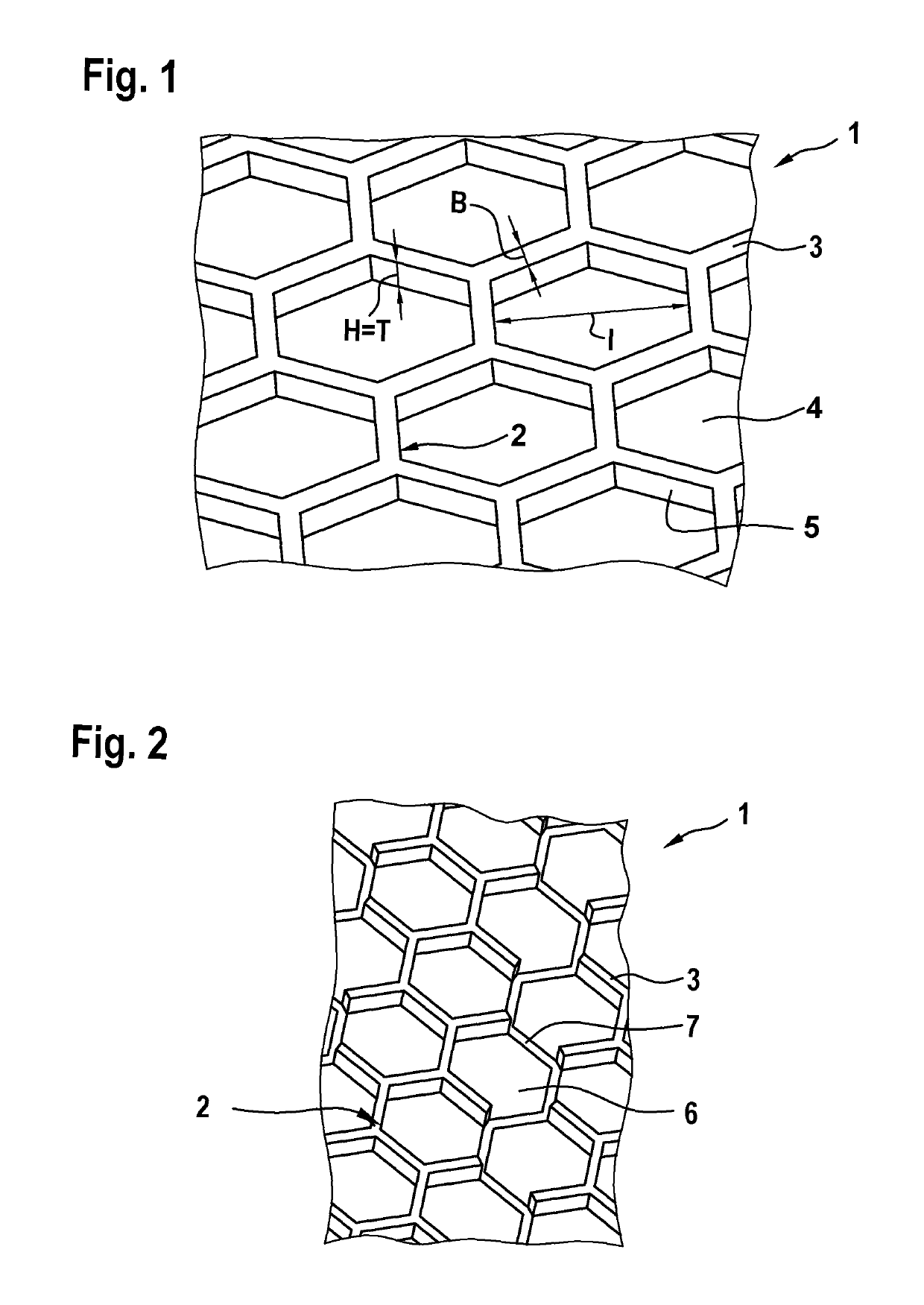
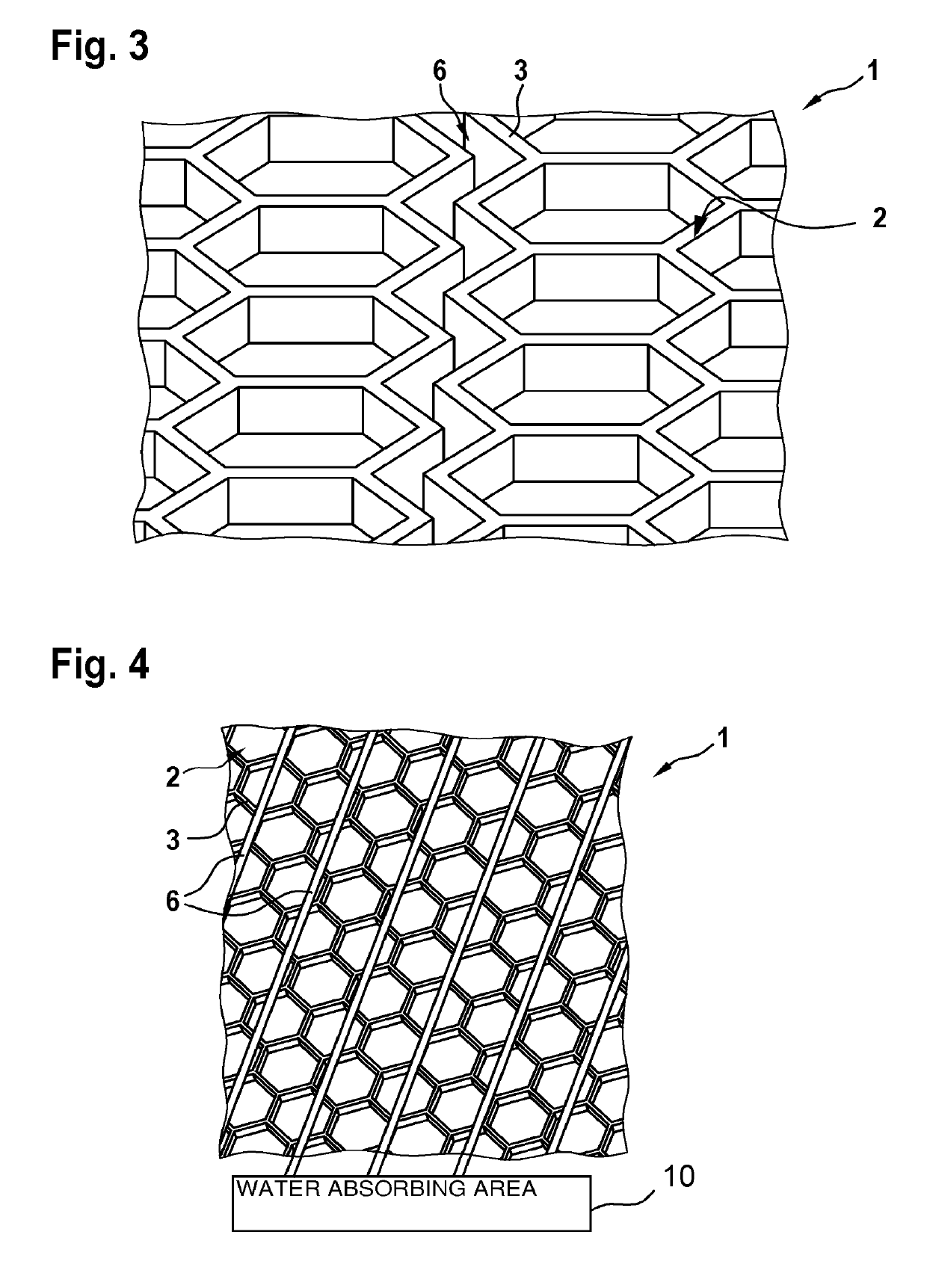
[0032]Referring to the drawings, FIG. 1 shows a detailed view of the honeycomb structure according to the present invention, which is generally designated by 1.

[0033]The honeycomb structure generally designated 1 has a plurality of honeycombs (honeycomb forms) generally designated 2 that are comprised of webs 3 that separate an interior space / interior area 4 of a honeycomb 2 from an interior space / interior area 4 of another honeycomb 2. FIG. 1 shows hexagonal recesses (interior space / interior area) 4 enclosed by webs 3 that are configured as honeycombs 2. The possible embodiments of the honeycombs are, however, not limited thereto. Rather, the honeycombs 2 may be polygonal, especially rectangular, hexagonal or octagonal. A round shape of the honeycombs as an embodiment variant is also possible. The structure 1 with honeycomb forms 2 can be produced via various manufacturing methods. Processes, which operate mechanically, chemically, by heat or concentrated light action as well as wi...


PUM

PropertyMeasurementUnit
inner widthaaaaaaaaaa
widthaaaaaaaaaa

Abstract

A component, especially an optical element, has a non-fogging surface. The surface has a honeycomb structure (1) with a plurality of honeycombs (2).

Description

CROSS REFERENCE TO RELATED APPLICATIONS[0001]This application claims the benefit of priority under 35 U.S.C. § 119 of German Application 10 2015 013 398.5 filed Oct. 19, 2015, the entire contents of which are incorporated herein by reference.FIELD OF THE INVENTION[0002]The present invention pertains to a component, and especially an optical element, with non-fogging surface.BACKGROUND OF THE INVENTION[0003]The fogging of surfaces, especially of optical elements, which is caused by condensation effects and precipitating moisture, is problematic in many respects. It is important not only in leisure areas, for example, in sports or in traffic, but also especially in safety engineering products that the operability of the components always be guaranteed. In objects of personal safety gear, for example, the visual capacity may be highly limited due to fogged mask disks, glasses and disks of protective suits due to condensation. As a result of a limited visibility, it could be that rescue...

Claims


Application Information

Patent Timeline
Patent Type & Authority Patents(United States)
IPC IPC(8): B32B3/12G02B27/00
CPCG02B27/0006B32B3/12B32B2551/00
Inventor WUSKE, THOMASUNGER, JURGENWENZEK, CATHARINASEIDL, TOBIAS
Owner DRAGER SAFETY
Why Eureka
Try Eureka