Eureka AIR delivers breakthrough ideas for toughest innovation challenges, trusted by R&D personnel around the world.

Face mask and method

a face mask and mask technology, applied in the field of face masks and respirators, can solve the problems of not intended to open the nasal passage beyond the normal conditions, respiratory discomfort, etc., and achieve the effects of reducing fatigue of surgeons, improving comfort, and reducing fatigu

Inactive Publication Date: 2006-07-18
BERKE JOSEPH J
View PDF9 Cites 27 Cited by
  • Summary
  • Abstract
  • Description
  • Claims
  • Application Information

AI Technical Summary

Benefits of technology

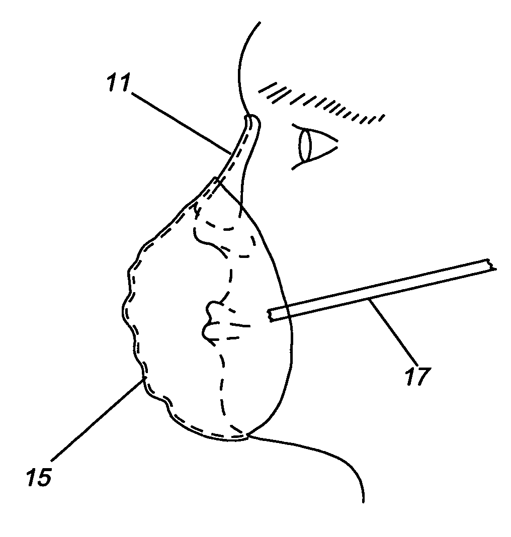
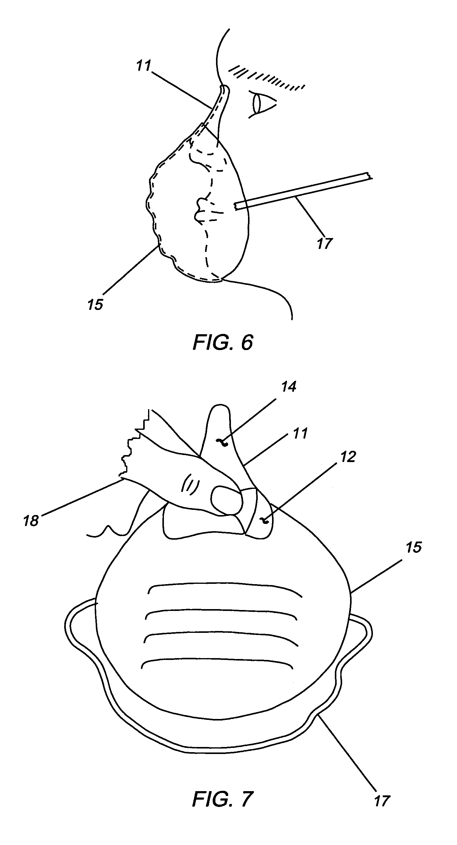
[0007]The primary object of the present invention is to promote a more comfortable and efficient air exchange in face masks and respirators by incorporating noseforms of the type disclosed in my U.S. Pat. No. 5,976,173. The noseform can be supplied as part of a mask or respirator or attached to a mask or respirator by a person with a usual method of joining, such as adhesion, heat bonding or sewing. One of the benefits of the invention is that the combined mask and noseform is effective with healthy as well as physically impaired persons suffering ailments such as nasal obstructions, asthma, and impaired heart and lungs. Another benefit is that it improves the comfort and reduces the fatigue of surgeons, nurses, and other medical persons in operating rooms. It also prevents fogging of glasses and it is relatively low in cost.

Problems solved by technology

This can cause respiratory discomfort, particularly in persons with medical conditions such as asthma, heart and lung ailments as well as healthy individuals under stress, in elevated temperatures and congested conditions, especially during prolonged surgery in operating rooms.
Although these dilators are intended to prevent nasal passage contractions, they are not intended to open nasal passages beyond their normal conditions.

Method used


Image

  • Face mask and method
  • Face mask and method
  • Face mask and method

Examples


Embodiment Construction

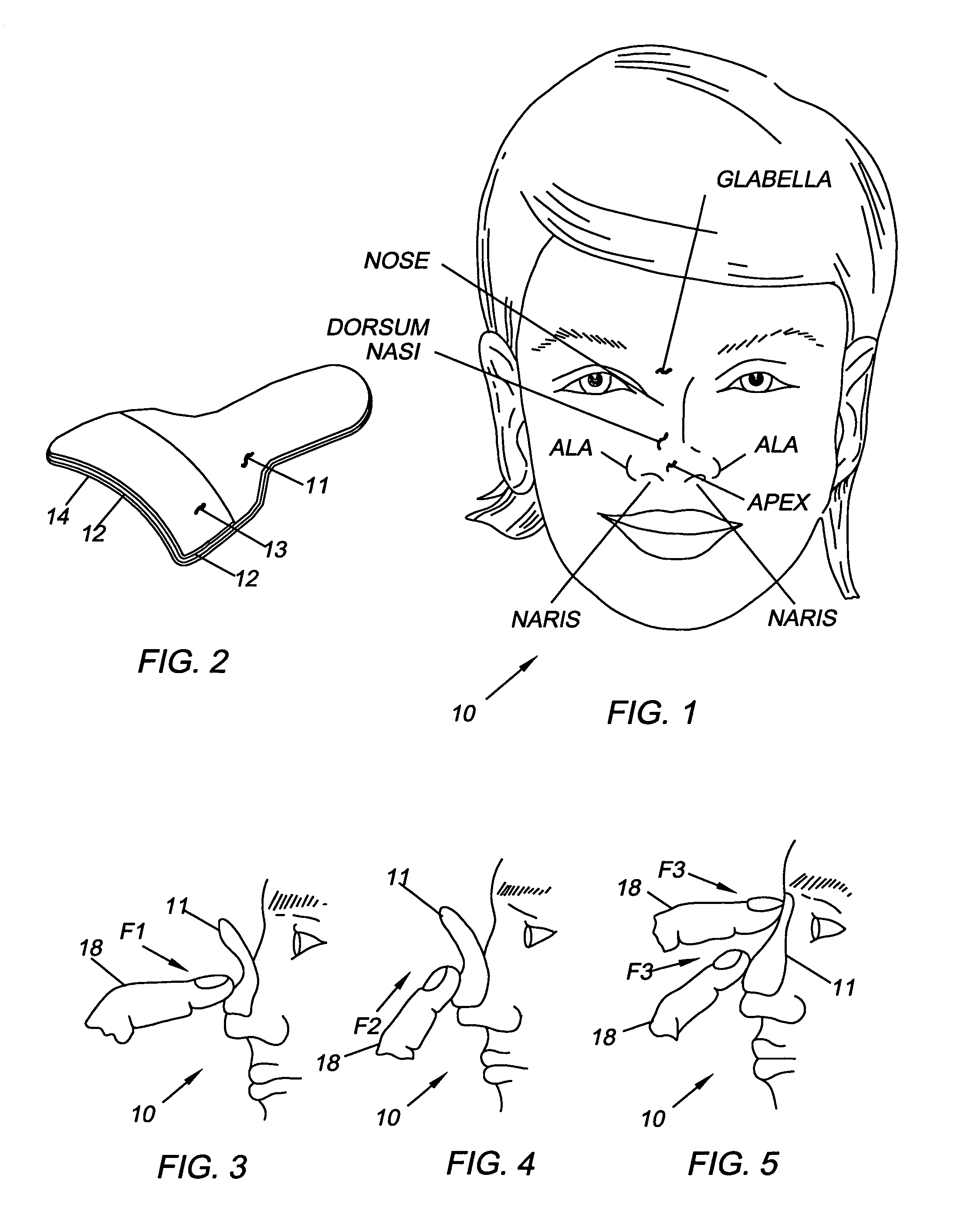
[0020]Referring now to the drawings wherein like numerals designate like and corresponding parts throughout the several views, in FIG. 1 a human face 10 is shown with designated features which are relevant to the present invention. A nose is covered with skin, which is movable in certain directions. The skin is movable along certain lines, referred to as Langers lines (not shown), which identify how the skin is movable. The lines along the nose run approximately transverse to the direction of the nose at approximately the center of the face. Thus, the skin of the nose is most easily moved from the nasal apex essentially vertically along the direction of the nose (this applies to the skin above the dorsal nose).

[0021]In FIG. 2 a noseform 11 is shown according to my U.S. Pat. No. 5,976,173 which is incorporated herein by reference. The noseform 11 is preferably made of a relatively thin, flexible elastic material. The noseform 11 has an adhesive coating 12 on an outer surface for adhe...


PUM


Abstract

A method for preventing a spread of diseases, promoting better breathing, improving comfort and reducing fatigue. The method utilizes a face mask and a noseform of the type disclosed in U.S. Pat. No. 5,976,173, which is incorporated herein by reference, In a first embodiment, the noseform is an integral part of a mask by forming, adhesion or heat bonding. In a second embodiment, the noseform is added to the mask prior to placing the mask in service with a usual method such as adhesion. In the first embodiment, the noseform is initially mounted on a person's nose by adhesively attaching the noseform to a lower portion of the nose, sliding the noseform upwardly toward the person's forehead and glabella and attaching an upper portion of the noseform to a fixed portion of the nose just below the glabella. The effect of this procedure is to shorten the person's airway and dilate the person's nasal passages. In the second embodiment, the noseform is initially mounted on a mask, followed by the steps of adhesively attaching the noseform to a lower portion of the nose, sliding the noseform upwardly toward the person's forehead and glabella and attaching an upper portion of the noseform to a fixed portion of the nose just below the glabella.

Description

FIELD OF THE INVENTION[0001]This invention relates to face masks and respirators and, more particularly to a face mask or respirator with a noseform and a method to prevent inhaling and exhaling harmful air borne substances, to prevent a spreading of contagious air borne substances, to improve breathing and to prevent a fogging of eyeglasses.BACKGROUND OF THE INVENTION[0002]Face masks and respirators are worn by medical and industrial workers to prevent inhaling and exhaling harmful air borne substances, such as, paints, solvents, dust particles, toxic fumes, smoke, bacteria and fungal spores. They are also worn to prevent spread of colds and air borne infections by covering the nose and mouth. They include filter elements, such as cotton gauze, fiberglass and fibrous paper filters that allow air to pass freely but prevent undesirable substances from passing through and prevent the spread of harmful bacteria at locations such as operating rooms. They also prevent individuals with di...

Claims


Application Information

Patent Timeline
Patent Type & Authority Patents(United States)
IPC IPC(8): A62B18/08
CPCA41D13/1176
Inventor BERKE, JOSEPH J.
Owner BERKE JOSEPH J
Why Eureka
Eureka Blog
Learn More