Zoom Lens, Imaging Optical Device, and Digital Apparatus
a technology of optical devices and zoom lenses, applied in the field of zoom lenses, can solve the problems of no lens unit suitable for damping vibration, and the inability to reduce the entire optical length at the telephoto end, so as to achieve high optical performance in damping vibration and reduce the entire optical length
- Summary
- Abstract
- Description
- Claims
- Application Information
AI Technical Summary
Benefits of technology
Problems solved by technology
Method used
Image

Examples
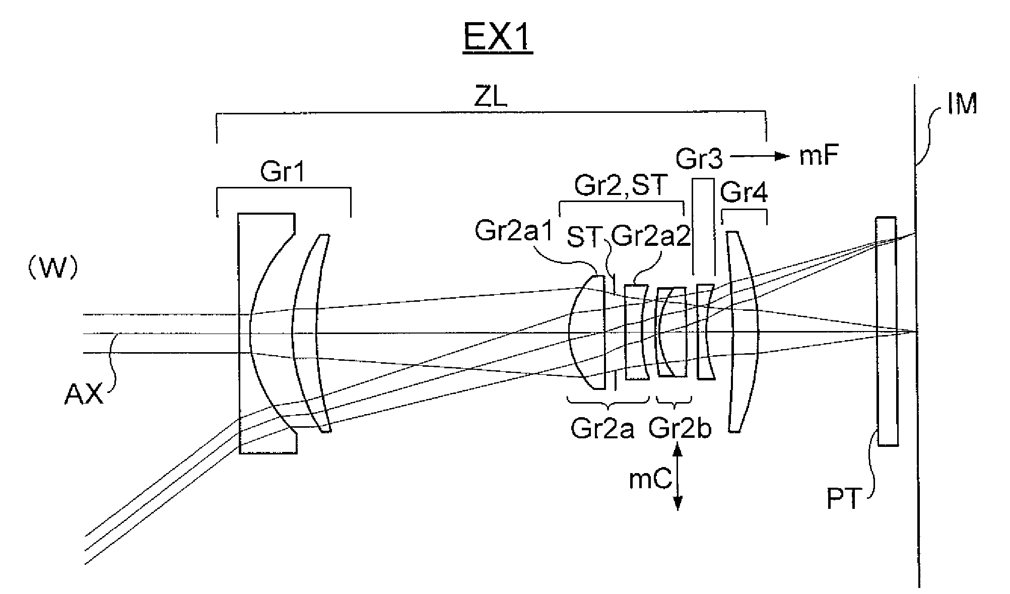
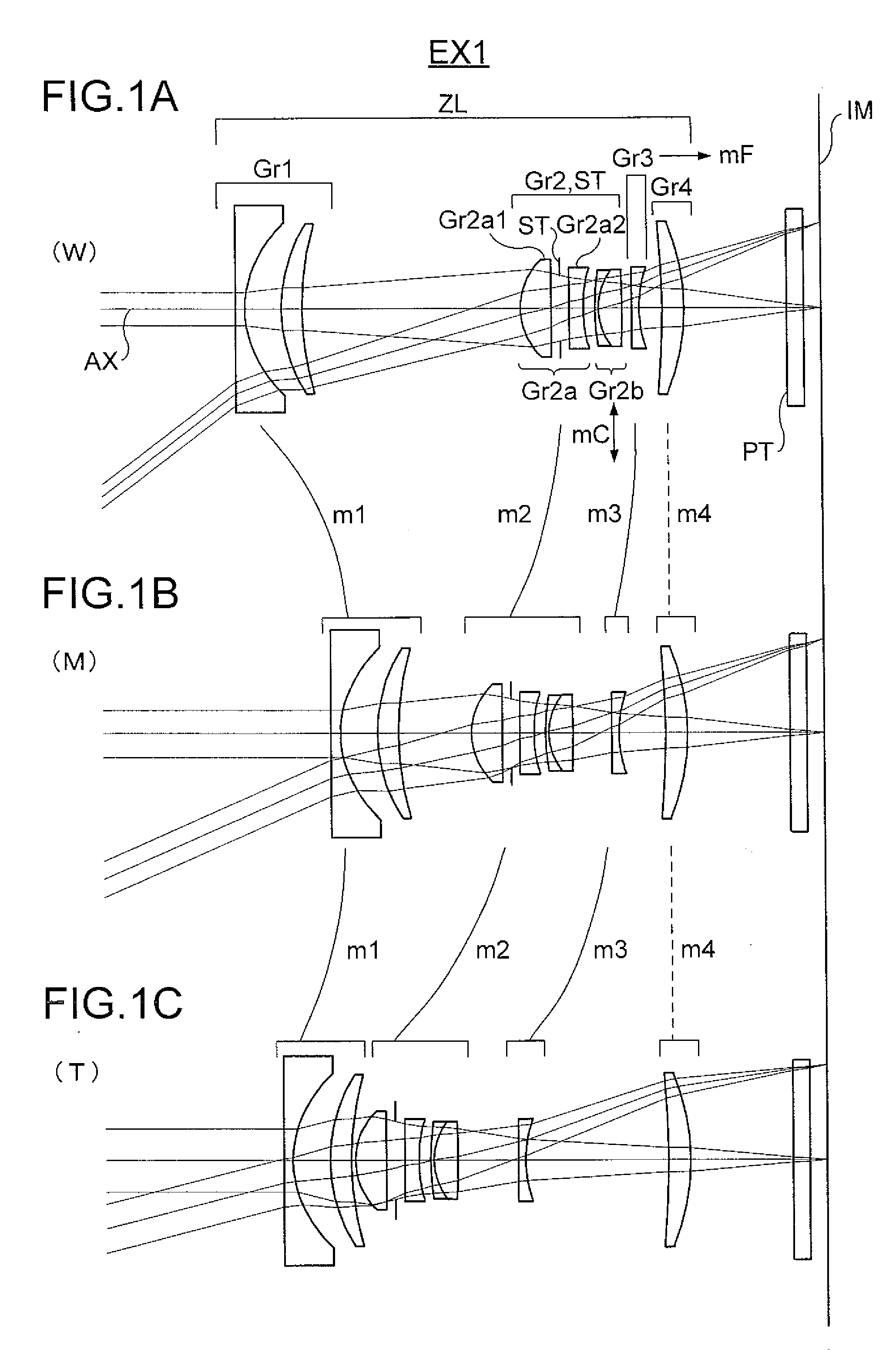
example 1
[0095]
Unit: mmSurface dataSurface numberrdndvd 1539.6321.1901.8042046.49 2*12.1594.331 318.8352.4301.8466623.78 434.946variable 5*7.8533.6001.4970081.61 6342.0621.045 7(stop)∞1.000 8200.2901.7401.8344137.28 9*24.0281.3441028.1690.4001.6200436.30117.2802.8601.6385455.4312−91.514variable13−149.0720.8001.5304855.7214*14.199variable15−96.1702.5601.8042046.4916−26.89712.100 17∞2.0001.5168064.2018∞BFAspheric surface dataSecond surfaceK = 0.00000A4 = −3.35989E−05A6 = −3.84200E−07A8 = 2.55853E−09A10 = −2.96843E−11Fifth surfaceK = 0.00000A4 = −1.44451E−05A6 = −6.27159E−07A8 = 2.62746E−08A10 = −4.40636E−10Ninth surfaceK = 0.00000A4 = 3.44172E−04A6 = 6.47376E−06A8 = −3.89285E−08A10 = 1.01322E−08Fourteenth surfaceK = 0.00000A4 = 2.30309E−05A6 = −7.37430E−07A8 = 5.67158E−08A10 = 1.24925E−09Various dataZoom ratio 3.000Wide angleIntermediateTelephoto(W)(M)(T)Focal length14.00024.20041.999F number3.6004.4005.700Half angle of view39.93223.57714.094Image height10.80010.80010.800Total lens length68.87...
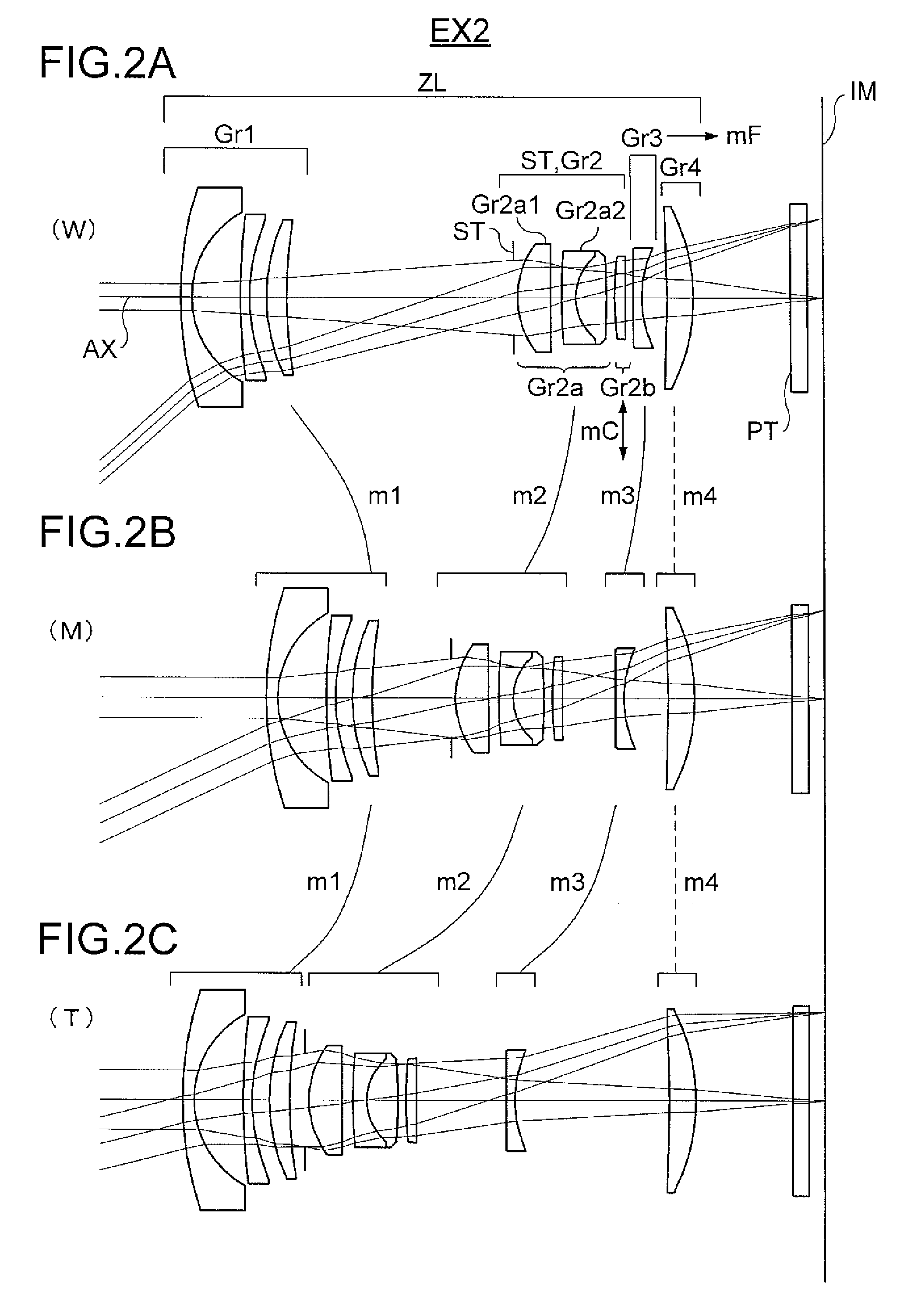
example 2
[0096]
Unit: mmSurface dataSurface numberrdndvd 143.4541.4001.7291654.66 212.1666.033 386.8161.1001.8348142.72 4*21.8852.084 522.9022.5001.8466623.78 658.836variable 7(stop)∞0.500 8*10.9194.1001.7737747.18 9*−314.0961.3171062.5721.7401.9036631.31116.7003.8501.4970081.6112−78.7861.0001344.5731.3001.8466623.7814507.123variable15507.1231.1001.5304855.7216*14.924variable17−221.6283.3501.6229958.1118−24.74312.100 19∞2.0001.5168064.2020∞BFAspheric surface dataFourth surfaceK = 0.00000A4 = −2.29360E−05A6 = −1.02931E−07A8 = 2.31746E−10A10 = −5.64920E−12Eighth surfaceK = 0.00000A4 = −3.73493E−05A6 = 3.56228E−07A8 = −1.57672E−08A10 = 1.43557E−10Ninth surfaceK = 0.00000A4 = 3.36398E−05A6 = 9.43525E−07A8 = −3.57707E−08A10 = 4.42346E−10Sixteenth surfaceK = 0.00000A4 = 4.15552E−05A6 = −7.78732E−07A8 = 9.35178E−09A10 = −2.62548E−10Various dataZoom ratio 3.500Wide angleIntermediateTelephoto(W)(M)(T)Focal length12.00022.40042.000F number3.6004.4005.700Half angle of view44.36125.17514.166Image height1...
example 3
[0097]
Unit: mmSurface dataSurface numberrdndvd 11429.6651.2501.8042046.49 2*12.5505.002 319.6042.4001.8466623.78 435.288variable 5(stop)∞0.500 6*8.3794.0001.4970081.61 7−217.3751.773 827.9300.5001.6727032.17 9*13.0513.8001019.5630.6001.6476933.841112.6552.2901.4970081.6112−65.404variable13150.7450.8001.5304855.7214*12.449variable15−39.0622.2701.8042046.4916−21.73812.100 17∞2.0001.5168064.2018∞BFAspheric surface dataSecond surfaceK = 0.00000A4 = −3.14807E−05A6 = −2.93044E−07A8 = 1.39119E−09A10 = −1.90131E−11Sixth surfaceK = 0.00000A4 = −1.79356E−05A6 = −7.18301E−07A8 = 1.19309E−08A10 = −3.82123E−10Ninth surfaceK = 0.00000A4 = 3.21205E−04A6 = 4.60161E−06A8 = 4.56187E−08A10 = 4.51866E−09Fourteenth surfaceK = 0.00000A4 = 1.59657E−05A6 = −7.72935E−07A8 = −1.29370E−08A10 = −4.05302E−11Various dataZoom ratio 3.000Wide angleIntermediateTelephoto(W)(M)(T)Focal length14.00024.20042.000F number3.6004.4005.700Half angle of view39.93923.47714.345Image height10.80010.80010.800Total lens length73....
PUM
 Abstract
Description
Claims
Application Information
 - R&D
- Intellectual Property
- Life Sciences
- Materials
- Tech Scout
- Unparalleled Data Quality
- Higher Quality Content
- 60% Fewer Hallucinations
Browse by: Latest US Patents, China's latest patents, Technical Efficacy Thesaurus, Application Domain, Technology Topic, Popular Technical Reports.
© 2025 PatSnap. All rights reserved.Legal|Privacy policy|Modern Slavery Act Transparency Statement|Sitemap|About US| Contact US: help@patsnap.com