Self-service terminal

Active Publication Date: 2013-01-31
NCR CORP
View PDF68 Cites 17 Cited by
  • Summary
  • Abstract
  • Description
  • Claims
  • Application Information

AI Technical Summary

Benefits of technology

[0012]The terminal head may be coupled to the terminal body (whether directly or indirectly) by an arm. The terminal head may be cantilevered from the terminal body by the arm (without resting on a floor or a base). One advantage of the

Problems solved by technology

However, not everyone uses ATMs.
For example, some people are not confident that they can operate an ATM correctly, perhaps due to a visual, physical, or cognitive impairment.
The traditional ATM design may not help such people to use ATMs, even when an ATM is located in

Method used


Image

  • Self-service terminal
  • Self-service terminal
  • Self-service terminal

Examples


Example

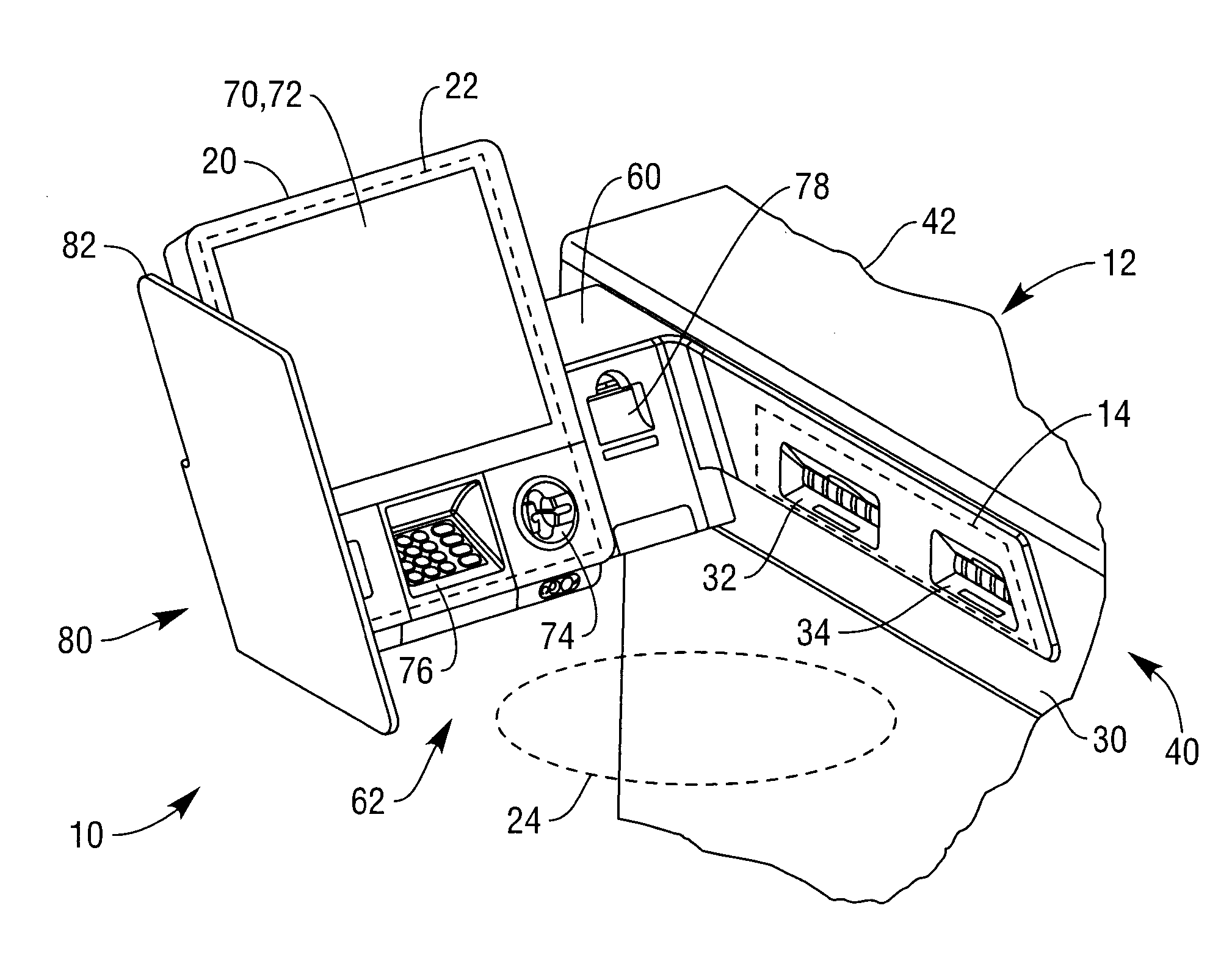
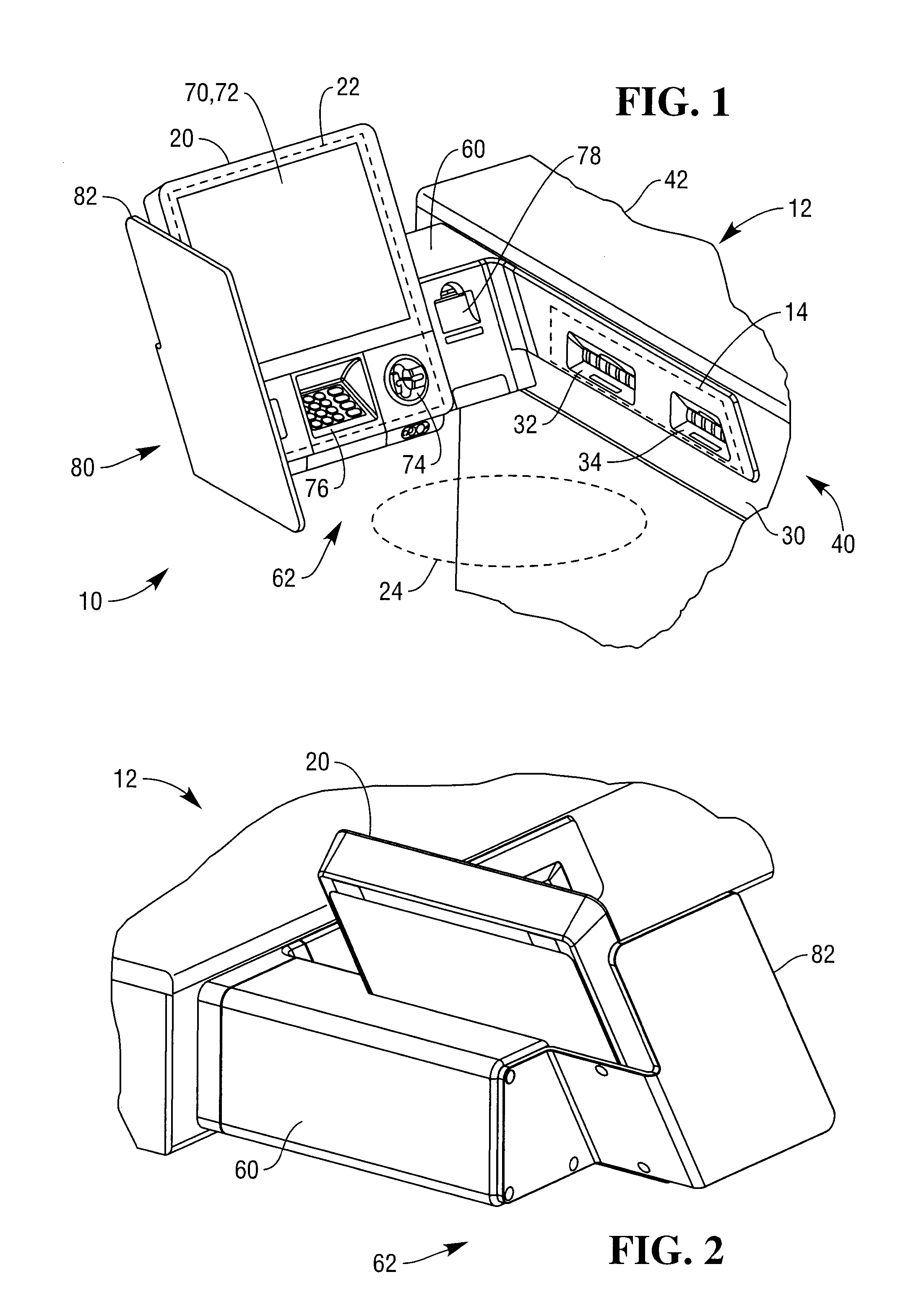
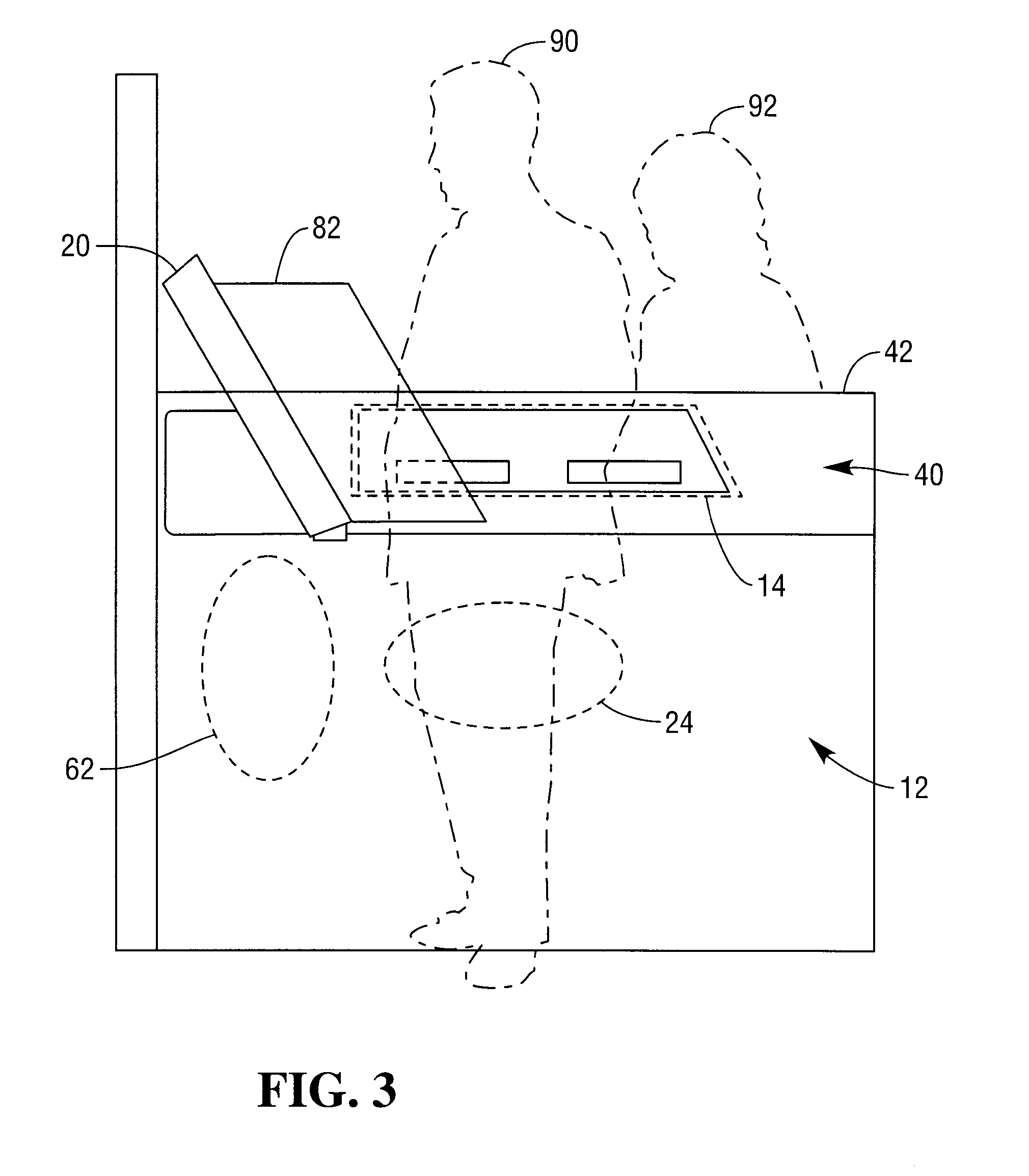
[0035]Reference is now made to the Figures. FIGS. 1 to 3 show a first embodiment, and FIGS. 4 and 5 show a second embodiment, very similar to the first embodiment. Many features of the first embodiment are common to the second embodiment, but may be more clearly visible on the second embodiment, so the description of the first embodiment may refer to features only visible on the second embodiment.

[0036]FIG. 1 is a pictorial front perspective view of a self-service terminal (SST) 10 according to one embodiment of the present invention. The SST 10 is in the form of an ATM. The ATM 10 comprises a terminal body 12 defining a transaction fulfillment area (indicated generally by broken line 14), and a terminal head 20 extending in a horizontal direction from the terminal body 12 and defining a transaction request area (indicated by arrow 22) transverse to the transaction fulfillment area 14. A customer zone (indicated generally by broken ellipse 24) is defined on one side by the transacti...


PUM


Abstract

A self-service terminal comprising: a terminal body defining a transaction fulfillment area, and a terminal head. The terminal head extends from the terminal body and defines a transaction request area transverse to the transaction fulfillment area. The transaction request area and transaction fulfillment area create a customer zone.

Description

FIELD OF INVENTION[0001]The present invention relates to a self-service terminal (SST), such as an automated teller machine (ATM).BACKGROUND OF INVENTION[0002]ATMs are commonplace and provide a reliable, quick, and secure mechanism for withdrawing cash and performing other financial transactions. However, not everyone uses ATMs. For example, some people are not confident that they can operate an ATM correctly, perhaps due to a visual, physical, or cognitive impairment. The traditional ATM design may not help such people to use ATMs, even when an ATM is located in a bank branch, because it is difficult to ask a member of staff for help without leaving the ATM. People in wheelchairs may also have difficulty using an ATM because some of the user interface elements may be too far away to be comfortably reached from a sitting position.SUMMARY OF INVENTION[0003]Accordingly, the invention generally provides an improved self-service terminal having a dispensing area within the terminal body...

Claims


Application Information

Patent Timeline
IPC IPC(8): G06Q40/02G07F19/00
CPCG07F19/20G06Q20/18G07F19/205G06Q20/10G06Q20/123G06Q20/20
Inventor COLLEY, ANDREWSWAINE, STEPHEN W.
Owner NCR CORP
Why Eureka
Try Eureka