Micro-gyroscope for detecting motions

a micro-gyroscope and motion detection technology, applied in the field of micro-gyroscopes, can solve the problems of high cost, difficult or impossible implementation of such sensors, and the driving of moving masses, and achieve the effect of high capture accuracy and reasonable cos

Active Publication Date: 2013-02-07
HANKING ELECTRONICS LTD
View PDF5 Cites 30 Cited by
  • Summary
  • Abstract
  • Description
  • Claims
  • Application Information

AI Technical Summary

Benefits of technology

[0009]The object of the present invention is to provide a 3D micro-gyrosensor that can be produced at a reasonable cost and having high capture accuracy, avoiding the unsuitable features indicated above, and that can be optionally designed so that two or three additional acceleration components can be captured simultaneously.

Problems solved by technology

The controls and analysis of the data are cost-intensive and required a great deal of effort.
The disadvantage hereby is that the production of such a sensor, as well as the driving of the moving masses, is difficult or impossible to implement.
The disadvantage hereby is that an inner plate and an outer ring are present, as well as four moving masses.
The spring constructions required, with low rigidity in two orthogonal directions of rotation, are sensitive to tolerances and difficult to implement.
Both proposed solution approaches are not suitable for simultaneously capturing accelerations along two or three orthogonal axes.

Method used


Image

  • Micro-gyroscope for detecting motions
  • Micro-gyroscope for detecting motions
  • Micro-gyroscope for detecting motions

Examples


Embodiment Construction

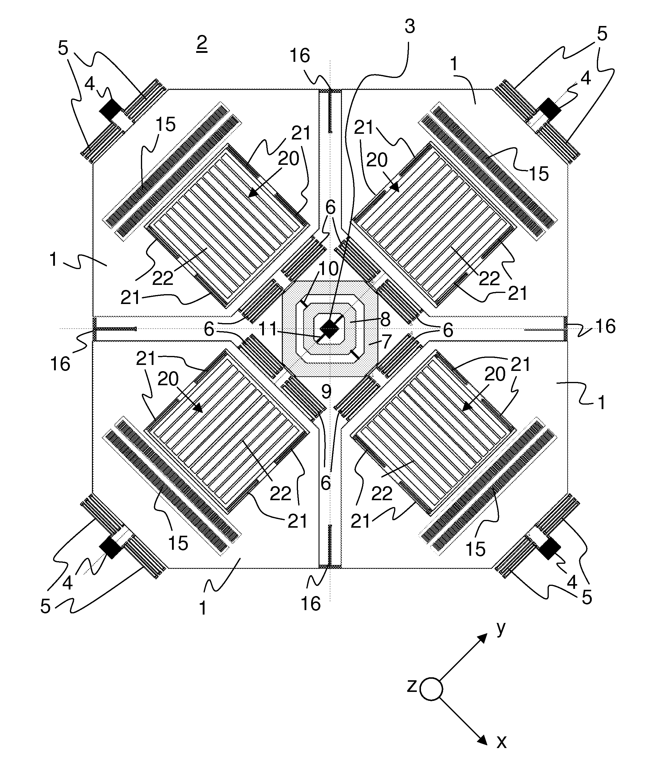
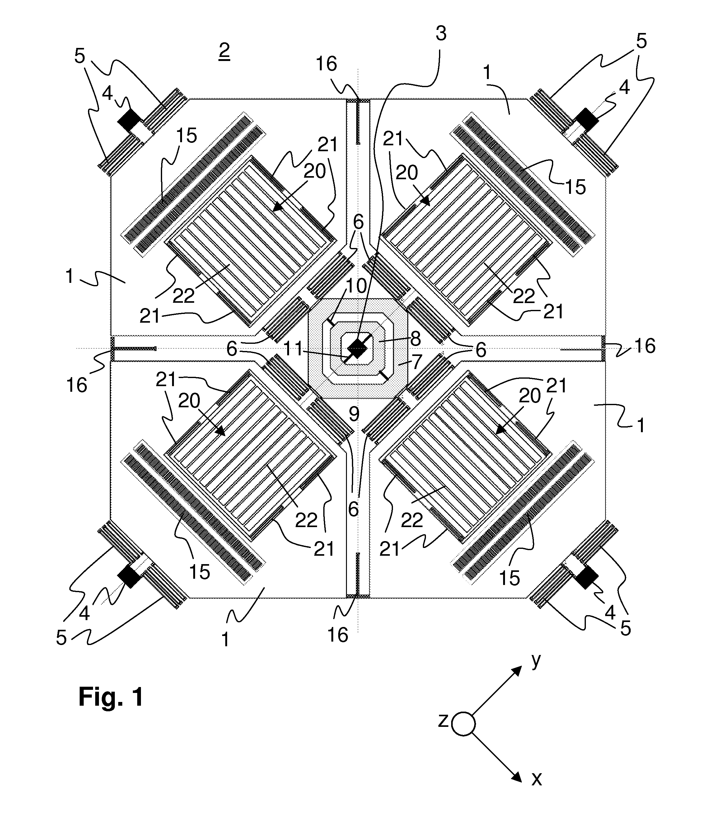
[0038]FIG. 1 shows a 3D gyroscope comprising four frames forming sample masses 1. The sample masses 1 are disposed in a plane above a substrate 2. They are connected to the substrate 2 by means of a central anchor 3 and one outer anchor 4 per sample mass 1. The connection to the outer anchor 4 is made by two outer anchor springs 5. Two inner anchor springs 6 and a gimbal mount 7 are disposed between the sample mass 1 and the central anchor 3. The outer anchor springs 5 and the inner anchor springs 6 are designed so that they allow an oscillating motion between the outer anchor 4 and the inner central anchor 3 within the drawing plane, that is, within an X-Y plane. In addition, the anchor springs 5 and 6 are designed such that they enable deflection orthogonal to the drawing plane, in order to be able to thereby indicate an X or Y rotational rate due to the Coriolis forces that arise. In order to achieve a certain level of stability of the sample mass 1 against tipping about the axis...


PUM


Abstract

The invention relates to a micro-gyroscope for detecting motions relative to an X and / or Y and Z axis, particularly as a 3D, 5D, or 6D sensor. Sample masses are disposed uniformly about an anchor and can be driven radially relative to the central anchor. Anchor springs are disposed to attach the sample masses to a substrate, and these sample masses can be deflected both radially within and out of the X-Y plane. A sensor mass is disposed on one of the sample masses by means of sensor springs, and the sensor springs allow deflection of the sensor mass within the plane of the sample mass, and orthogonal to the radial drive direction of the sample masses. Drive elements oscillate these sample masses in the X-Y plane, and sensor elements captures the defection of the sample masses due to the Coriolis forces generated when the substrate is rotated.

Description

CROSS REFERENCE TO RELATED APPLICATIONS[0001]This application is the National Phase Application under 35 USC §371 of International Application No. PCT / EP2011 / 056267, filed Apr. 19, 2011, which claims priority to German Patent Application No. 10 2010 028 005.4, filed Apr. 20, 2010.BACKGROUND[0002]A. Technical Field[0003]The present invention relates to a micro-gyroscope for detecting motions relative to an X and / or a Y and a Z axis, particularly as a 3D, 5D, or 6D sensor, having a substrate, having a plurality of oscillating sample masses, having anchors and anchor springs disposed between the anchor and drive mass for attaching the oscillating sample masses to the substrate, having drive elements for oscillating the sample masses in the X-Y plane, in order to generate Coriolis forces during a rotary motion of the substrate and to capture deflections of the sample masses due to the Coriolis forces generated from the X or Y rotation rates using sensor elements, particularly electrodes...

Claims


Application Information

Patent Timeline
Patent Type & Authority Applications(United States)
IPC IPC(8): G01C19/56G01C19/5747
CPCG01C19/5747G01C19/56G01C19/5642G01C19/5656G01C19/5719
Inventor KEMPE, VOLKER
Owner HANKING ELECTRONICS LTD
Why Eureka
Try Eureka