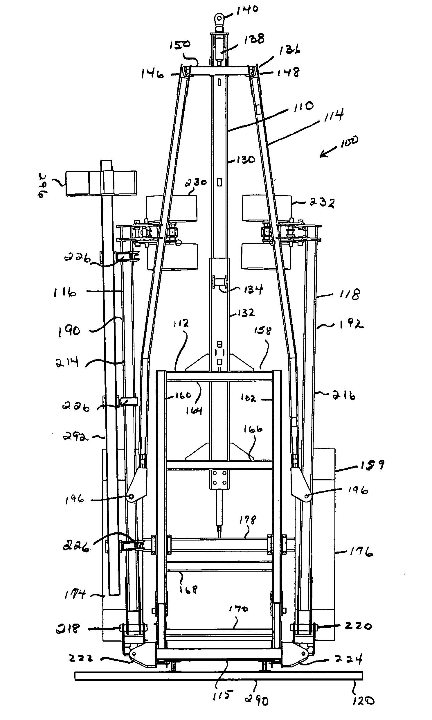
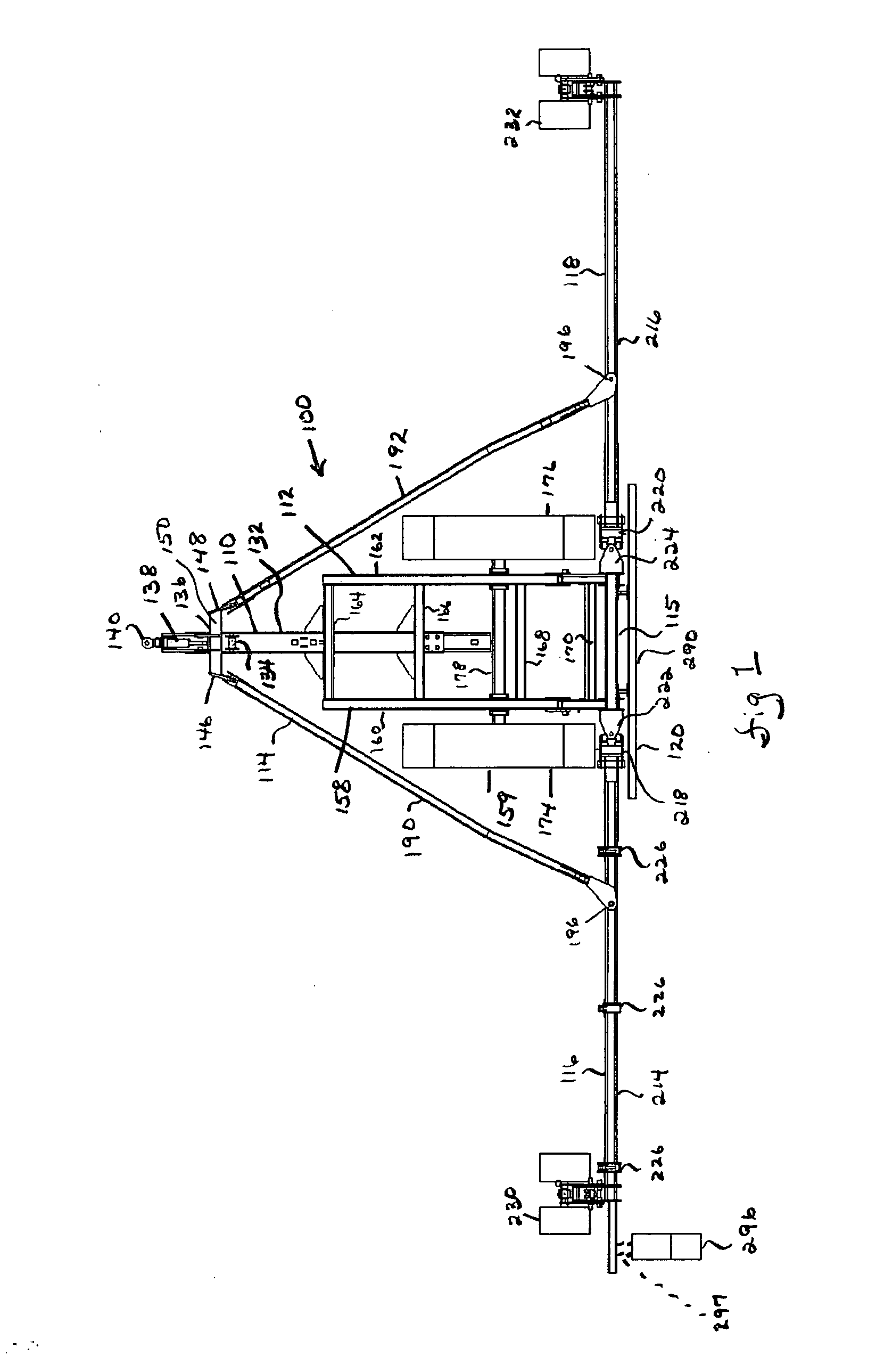
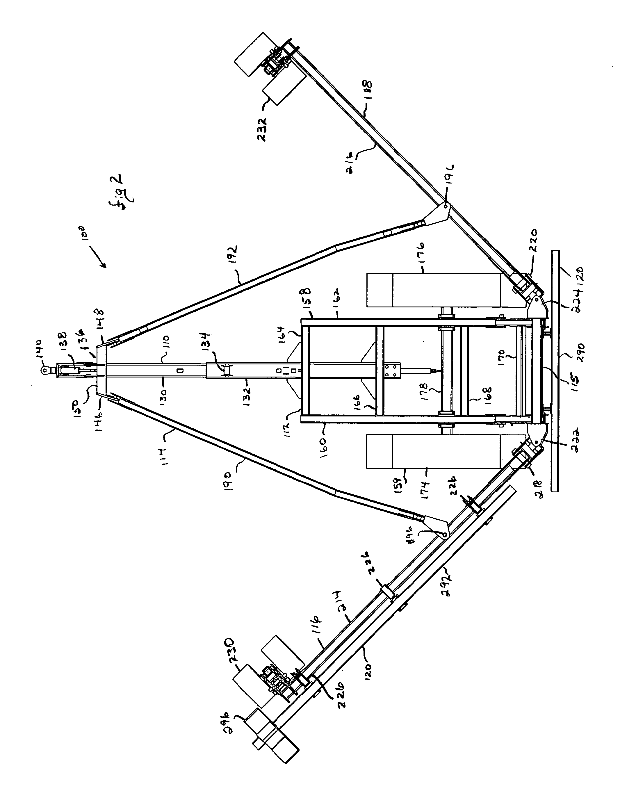
Implement convertible between use configuration and transport configuration
a technology of transport configuration and use configuration, applied in the field of agricultural implements, can solve the problems of complex operation mechanism and structural support framework, subject to use and wear, and large volume and weight, and achieve the effect of minimizing reducing production costs, and reducing the stress on the other frame components
- Summary
- Abstract
- Description
- Claims
- Application Information
AI Technical Summary
Benefits of technology
Problems solved by technology
Method used
Image

Examples
Embodiment Construction
[0061]Unless otherwise defined, all technical and scientific terms used herein have the same meaning as commonly understood by one of ordinary skill in the art to which this invention belongs. Although methods and materials similar or equivalent to those described herein can be used to practice the invention, suitable methods and materials are described below. Any references to such relative terms as forward and rearward, front and back, right and left, top and bottom, upper and lower, horizontal and vertical, or the like, are intended for convenience of description and are not intended to limit the present invention or its components to any one positional or spatial orientation.
[0062]Each of the additional features and methods disclosed herein may be utilized separately or in conjunction with other features and methods to provide improved connectors and methods for making the same. Indeed, a person of ordinary skill in the art will readily appreciate that individual components show...
PUM
 Abstract
Description
Claims
Application Information
 - R&D
- Intellectual Property
- Life Sciences
- Materials
- Tech Scout
- Unparalleled Data Quality
- Higher Quality Content
- 60% Fewer Hallucinations
Browse by: Latest US Patents, China's latest patents, Technical Efficacy Thesaurus, Application Domain, Technology Topic, Popular Technical Reports.
© 2025 PatSnap. All rights reserved.Legal|Privacy policy|Modern Slavery Act Transparency Statement|Sitemap|About US| Contact US: help@patsnap.com