
Adaptive speed pay automotive module

a technology of automotive modules and speed pay, applied in the field of communication devices, can solve problems such as unauthorized parties taking private data belonging to users, and affecting the performance of the system, and achieve the effect of reducing the risk of data th

Inactive Publication Date: 2013-02-07
OMRON AUTOMOTIVE ELECTRONICS CO LTD
View PDF9 Cites 4 Cited by
  • Summary
  • Abstract
  • Description
  • Claims
  • Application Information

AI Technical Summary

Benefits of technology

The present patent is about a communication device that can be used with a speed pay system. The device has two parts, a controller and a communication element. When the two parts are attached together, they can use the speed pay system. When the two parts are detached, the operation of the device with the speed pay system is disabled. This allows for quick and easy use of the speed pay system with the communication device.

Problems solved by technology

One problem associated with such devices having speed / quick pay electronics is that private data belonging to a user, which may be stored on the device having speed / quick pay electronics, may be taken by unauthorized parties.

Method used


Image

  • Adaptive speed pay automotive module
  • Adaptive speed pay automotive module
  • Adaptive speed pay automotive module

Examples


Embodiment Construction

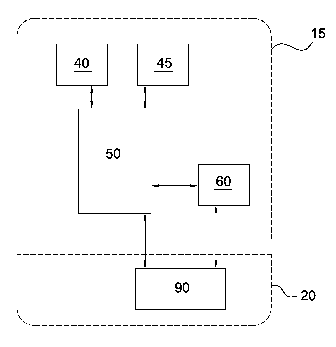
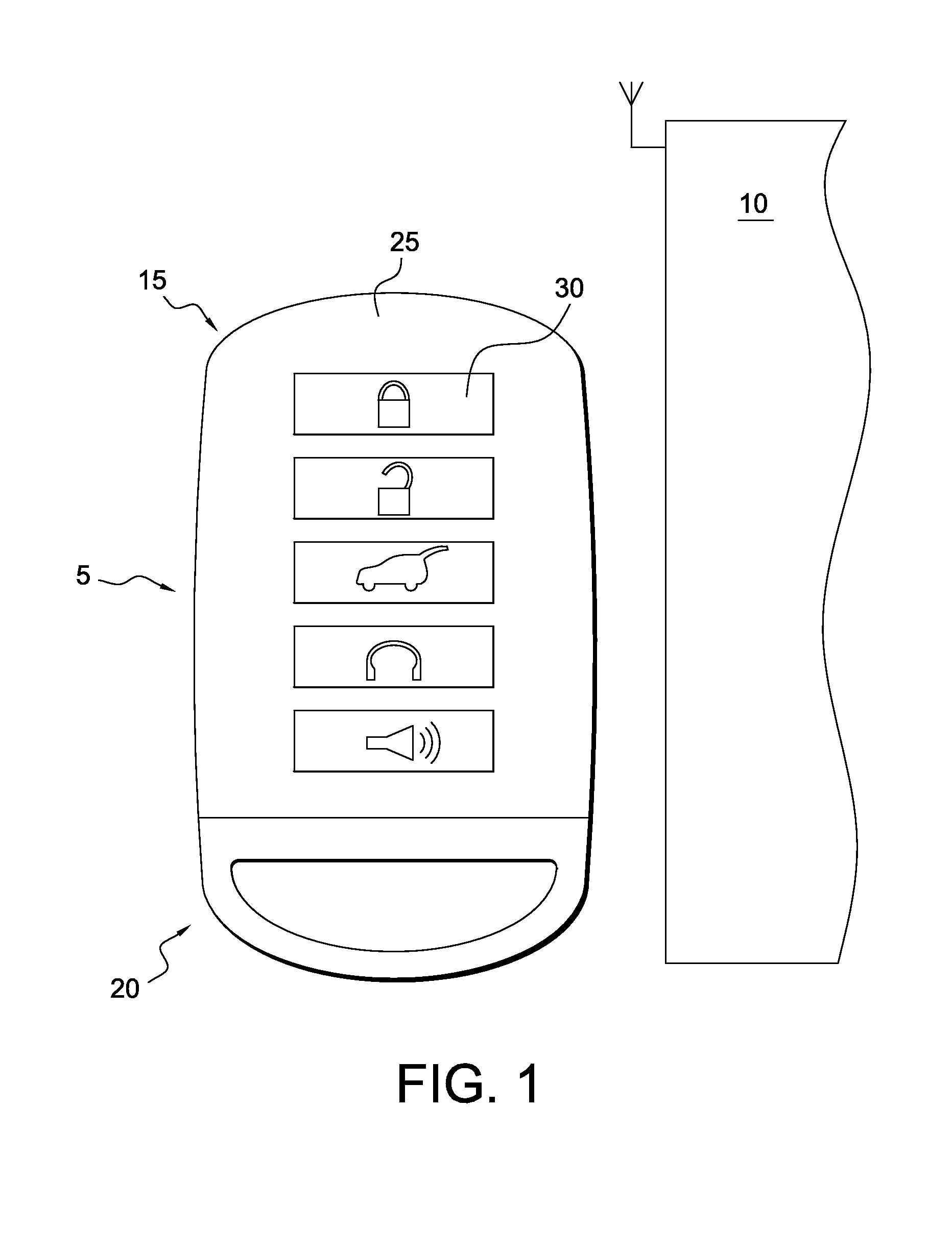
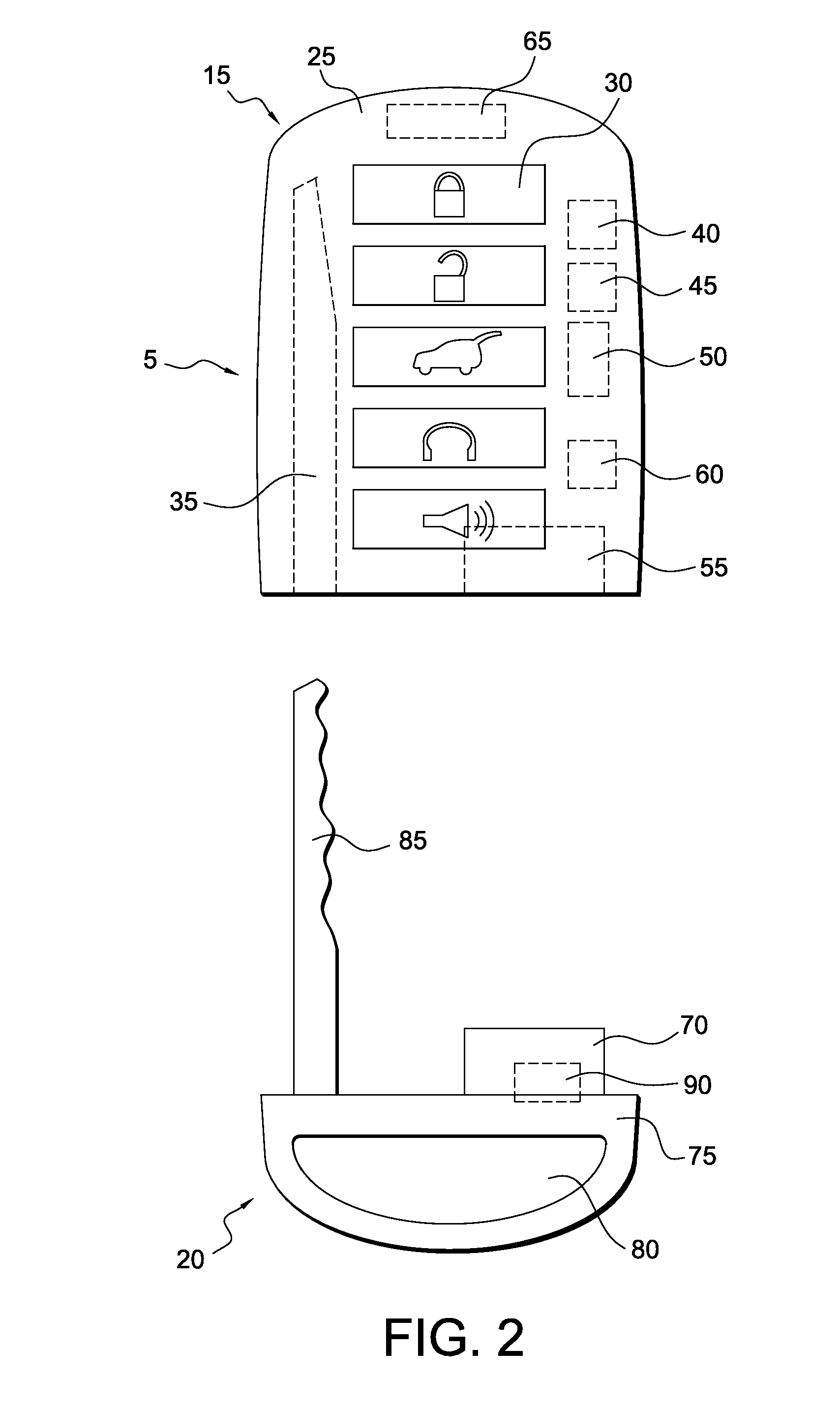
[0011]FIG. 1 illustrates an exemplary disclosed communication device 5. Communication device 5 may be, for example, a communication device associated with a user-operated assembly 10 such as a vehicle. For example, communication device 5 may be a device that allows a user to remotely operate functions of a user-operated assembly 10 such as, for example, a vehicle. For example, in one exemplary embodiment, communication device 5 may be a keyfob for a passenger vehicle. Communication device 5 may include a first assembly 15 and a second assembly 20. First assembly 15 and second assembly 20 may be removably attachable to each other, and may each work independently and in combination to control user-operated assembly 10.

[0012]As illustrated in FIGS. 1 and 2, first assembly 15 may include a body 25, one or more input elements 30, a cavity 35, a first communication element 40, a second communication element 45, a controller 50, a connector 55, a third communication element 60, and a power...


PUM


Abstract

A communication device is disclosed. The communication device has a first assembly including a controller, a first communication element, and a speed pay communication element. The controller is configured to use the first communication element to control an operation of a user-operated assembly. The communication device also has a second assembly including an electronics element configured to operate with a speed pay system. The second assembly is removably attachable to the first assembly. The controller, the speed pay communication element, and the electronics element are configured to operate with the speed pay system when the first assembly and the second assembly are attached to each other. The operation of the communication device with the speed pay system is disabled when the first assembly and the second assembly are detached from each other.

Description

[0001]This application is a Continuation of U.S. application Ser. No. 13 / 194,680, filed on Jul. 29, 2011, which claimed the benefit of domestic priority of U.S. provisional application 61 / 368,932, filed Jul. 29, 2010, the subject matters of which are incorporated herein by reference.TECHNICAL FIELD[0002]This disclosure is directed to a communication device and, more particularly, to a communication device that operates with a speed / quick pay system.BACKGROUND[0003]Speed / quick pay systems have become increasingly prevalent in the marketplace. Using speed / quick pay systems, users may use a device having speed / quick pay electronics to quickly make transactions such as, for example, financial transactions.[0004]One problem associated with such devices having speed / quick pay electronics is that private data belonging to a user, which may be stored on the device having speed / quick pay electronics, may be taken by unauthorized parties. For example, if a third party gains access to a device...

Claims


Application Information

Patent Timeline
Patent Type & Authority Applications(United States)
IPC IPC(8): G05B19/00
CPCG05B19/00G07C9/00174G07C9/00944G07C2009/00952
Inventor KURTZ, MICHAELDZIABA, STEFANCANNEK, LARRY
Owner OMRON AUTOMOTIVE ELECTRONICS CO LTD
Learn More