
Drill rig and method for operating a drill rig

a drill rig and a technology for drilling rigs, applied in the direction of instruments, computer control, borehole/well accessories, etc., can solve the problems of increasing the chance of a catastrophic failure, introducing additional dangers to an already dangerous operation, and enhancing portability

Active Publication Date: 2019-02-14
NIELD BARRY J +1
View PDF14 Cites 3 Cited by
  • Summary
  • Abstract
  • Description
  • Claims
  • Application Information

AI Technical Summary

Benefits of technology

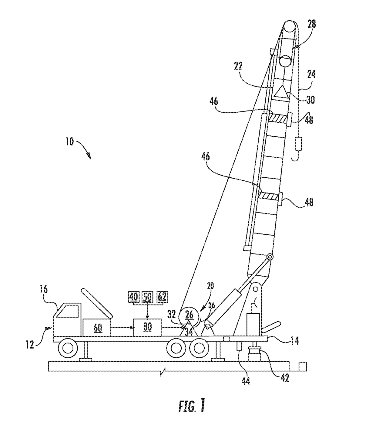
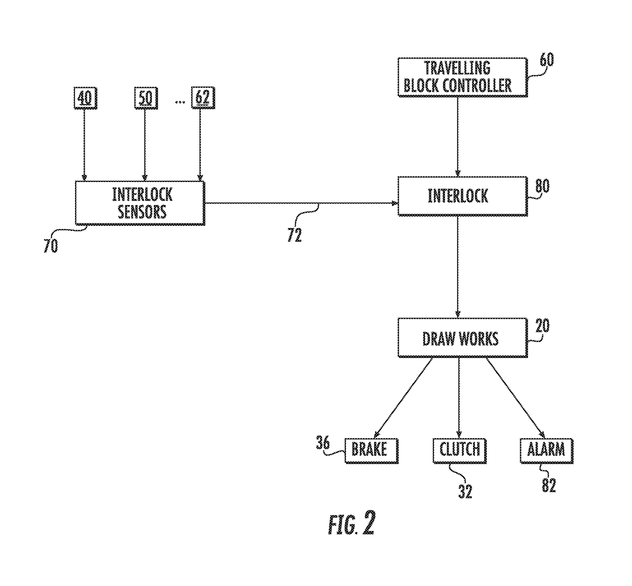
This patent describes a drill rig with a drawworks that has a brake and a traveling block that can hold a drill string. The drill string can be released or retracted by operating the drawworks, which is controlled by a traveling block controller. An interlock sensor can detect various parameters of the drill rig and generate an interlock signal based on those parameters. An interlock is connected to the traveling block controller and can disable the operation of either the traveling block controller or the drawaws if the interlock signal meets certain criteria. The technical effect of this invention is to improve the safety and efficiency of drill rig operations by preventing unauthorized or unsafe operations.

Problems solved by technology

While the mobile platform enhances portability of the drill rig to various locations, the enhanced portability also introduces additional dangers to an already dangerous operation.
While additional procedures may be implemented to address these and other additional dangers, inadvertent errors or procedural omissions may increase the chance of a catastrophic failure.

Method used


Image

  • Drill rig and method for operating a drill rig
  • Drill rig and method for operating a drill rig
  • Drill rig and method for operating a drill rig

Examples


Embodiment Construction

[0015]Reference will now be made in detail to present embodiments of the invention, one or more examples of which are illustrated in the accompanying drawings. The detailed description uses numerical and letter designations to refer to features in the drawings. Like or similar designations in the drawings and description have been used to refer to like or similar parts of the invention. Each example is provided by way of explanation of the invention, not limitation of the invention. In fact, it will be apparent to those skilled in the art that modifications and variations can be made in the present invention without departing from the scope or spirit thereof. For instance, features illustrated or described as part of one embodiment may be used on another embodiment to yield a still further embodiment. Thus, it is intended that the present invention covers such modifications and variations as come within the scope of the appended claims and their equivalents.

[0016]Embodiments of the ...


PUM


Abstract

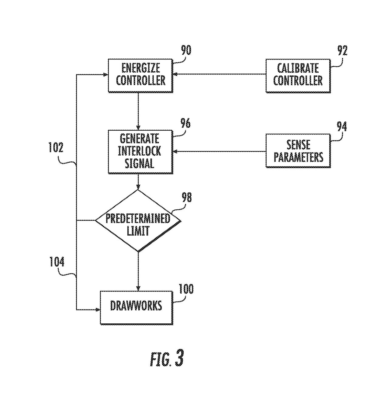
A drill rig includes a drawworks having a drum operably connected to a drive system and a brake. A drill string extends from the drum of the drawworks, along a derrick, to a block and tackle arrangement holding a travelling block so that operation of the drawworks causes the drum to release or retract the drill string. A travelling block controller controls the operation of the drawworks. An interlock sensor senses a sensed parameter, and the sensed parameter is at least one of a drill rig parameter, a drawworks parameter, or a travelling block controller parameter. An interlock signal generated by the interlock sensor is reflective of the sensed parameter. An interlock operably connected to the travelling block controller receives the interlock signal and disables operation of at least one of the travelling block controller or the drawworks if the interlock signal meets a predetermined criteria.

Description

FIELD OF THE INVENTION[0001]The present invention generally involves a drill rig and a method for operating the drill rig. Particular embodiments of the present invention may be incorporated into land-based or offshore drill rigs used for gas production and / or well service operation to reduce or prevent personnel injury or equipment damage during manual or automatic operation of the drill rig.BACKGROUND OF THE INVENTION[0002]Drill rigs are commonly used in oil and gas production and well service operations to bore substantial distances below the earth's surface. A drill rig generally includes a drawworks for raising and lowering a drill string in a borehole. The drawworks generally includes a large drum or spool that holds the drill string. The drill string extends from the drum to a derrick that supports a block and tackle arrangement holding a travelling block. The travelling block provides a mechanical advantage for raising and lowering the drill string in the borehole. A clutch ...

Claims


Application Information

Patent Timeline
Patent Type & Authority Applications(United States)
IPC IPC(8): E21B41/00G05B15/02E21B7/02
CPCE21B41/0021G05B15/02E21B44/00E21B7/022E21B7/024
Inventor NIELD, BARRY J.NIELD, GEORGE A.
Owner NIELD BARRY J
Learn More