Wheel slip brake assurance module

Inactive Publication Date: 2007-09-20
WABTEC HLDG CORP
View PDF20 Cites 5 Cited by
  • Summary
  • Abstract
  • Description
  • Claims
  • Application Information

AI Technical Summary

Benefits of technology

[0009] It is an object of this invention to provide a system to ensure that brake cylinder pressure is available in the event that wheel slip control is not effective or inoperative due to hardware and/or software component failure. It is a further object of this invention to provide a pneumatic assurance module for independently monitoring and controlling brake cylinder pressure as controlled by the wheel slip valve. It is a still further object of this invention to ensure that wheel slip control is limited against extended periods of brake pressure reduction without appropriate periods of brake application.
[0010] Briefly, according to this invention, there is provided an improvement in a pneumatic brake cylinder control circuit for controlling the supply of pressurized air to brake cylinders. In a pneumatic brake cylinder control circuit for controlling the supply of pressurized air to brake cylinders, the circuit has a main source of pressurized air and a wheel slip circuit comprising a wheel slip valve having two magnet valves for directing flow from a pilot pressure port to pneumatically-actuated release and lap valves. The wheel slip valve connects a source of brake control pressure to the brake cylinders, exhausts the cylinders, or maintains the pressure in the cylinders in response to electrical signals from a wheel slip sensing unit.
[0011] The improvement according to this invention is a pneumatic timing circuit controlled by the pressure at the output of the wheel slip valve. The pneumatic pressure at the output of the wheel slip valve charges and discharges the pneumatic timing circuit. When the pressure in the pneumatic timing circuit has discharged to a selected level based upon the ave

Problems solved by technology

Thus, if the reservoir pressure falls below the pilot pressure that holds the transfer valve in the enabled position, the pilot pressure of the wheel slip valve will be exhausted and slip control will be interrupted.

Method used


Image

  • Wheel slip brake assurance module
  • Wheel slip brake assurance module
  • Wheel slip brake assurance module

Examples


Embodiment Construction

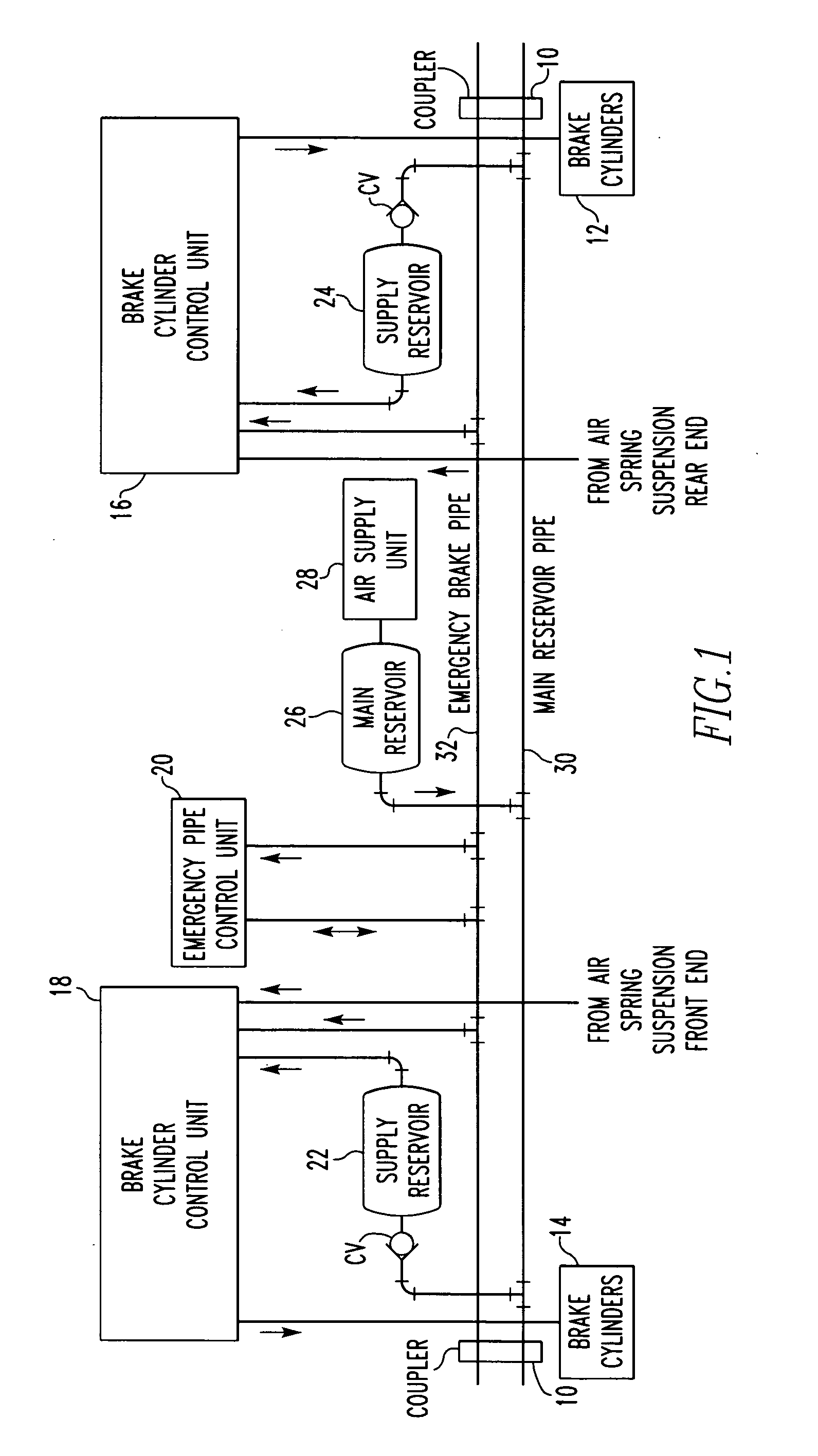
[0018] Referring now to FIG. 1, the transit vehicle has a coupler 10 at each end that mechanically couples adjacent vehicles and provides coupling of the emergency brake pipe 32 and main reservoir pipe 30, as well as electrical train lines. The main reservoir and emergency (brake) pipe are the source of pneumatic pressure for implementing service and emergency braking. The pipes, along with the electrical train line, implement the combined electrical and pneumatic (electro-pneumatic) braking control.

[0019] As shown in FIG. 1, the transit vehicle has brake cylinders 12, 14, for each truck of the car for actuating brakes, such as disc or tread-type brakes, associated with each wheel axle. Each truck's brakes are controlled primarily by a Brake Cylinder Control Unit (BCCU) 16, 18. The BCCUs respond to service braking commands and emergency braking commands generated by local control systems, such as the Emergency Pipe Control Unit (EPCU) 20, friction brake control units, and train lin...


PUM


Abstract

A wheel slip assurance module comprises a device for disabling the wheel slip valve, a timing reservoir in communication with the disabling device, and a check valve and choke circuit providing parallel connections between the output of the wheel slip valve and the timing reservoir having a first connection path comprising a check valve and charging choke and a second connection path comprising a dissipating choke such that flow from the output of the wheel slip valve passes through the check valve and charging choke to charge the reservoir when the brake cylinders are pressurized and opposite flow passes through the dissipating choke allowing the reservoir to discharge when the brake cylinders are exhausted.

Description

BACKGROUND OF THE INVENTION [0001] 1. Field of the Invention [0002] This invention relates to wheel slip control safety timers that can suspend a wheel slip control operation. [0003] 2. Description of Related Art [0004] It is well known in the brake control art that modern train brake control systems typically use a central controller unit to control the brakes of the rail vehicles that comprise the train. A train operator located in the lead cab manipulates the brake handles or like devices of the train to apply and release the brakes of the trucks or bogies on each rail vehicle as desired. The inputs from the brake handles are typically processed by a cab control unit and passed to the central controller unit. In response to these and other inputs, the central controller unit issues a brake command signal along a train line to each of the rail vehicles in the form of either a pneumatic signal or an electrical signal or even both. Brake equipment on each of the rail vehicles applie...

Claims


Application Information

Patent Timeline
IPC IPC(8): B60T8/74
CPCB60T17/228B60T8/3235
Inventor SCHWEIKERT, DAVID E.SCHARPF, ROBERT N.WOOD, JAMES A.
Owner WABTEC HLDG CORP
Why Eureka
Try Eureka