
Scanner

a scanner and scanner technology, applied in the field of scanners, can solve the problem that the conventional scanner can only be connected to the computing device via a connecting cable or a wire, and achieve the effect of viewing the scanned image data with ease and convenien

Inactive Publication Date: 2013-02-07
MUSTEK SYSTEMS
View PDF6 Cites 4 Cited by
  • Summary
  • Abstract
  • Description
  • Claims
  • Application Information

AI Technical Summary

Benefits of technology

The present invention allows for easier connection between a portable electronic device with image display functionality and a scanner. This allows for convenient and easy viewing of scanned image data.

Problems solved by technology

However, the conventional scanner can only be connected to a computing device via a connecting cable or a wire.

Method used


Image

  • Scanner
  • Scanner
  • Scanner

Examples


Embodiment Construction

[0036]Before the present invention is described in greater detail, it should be noted that like elements are denoted by the same reference numerals throughout the disclosure.

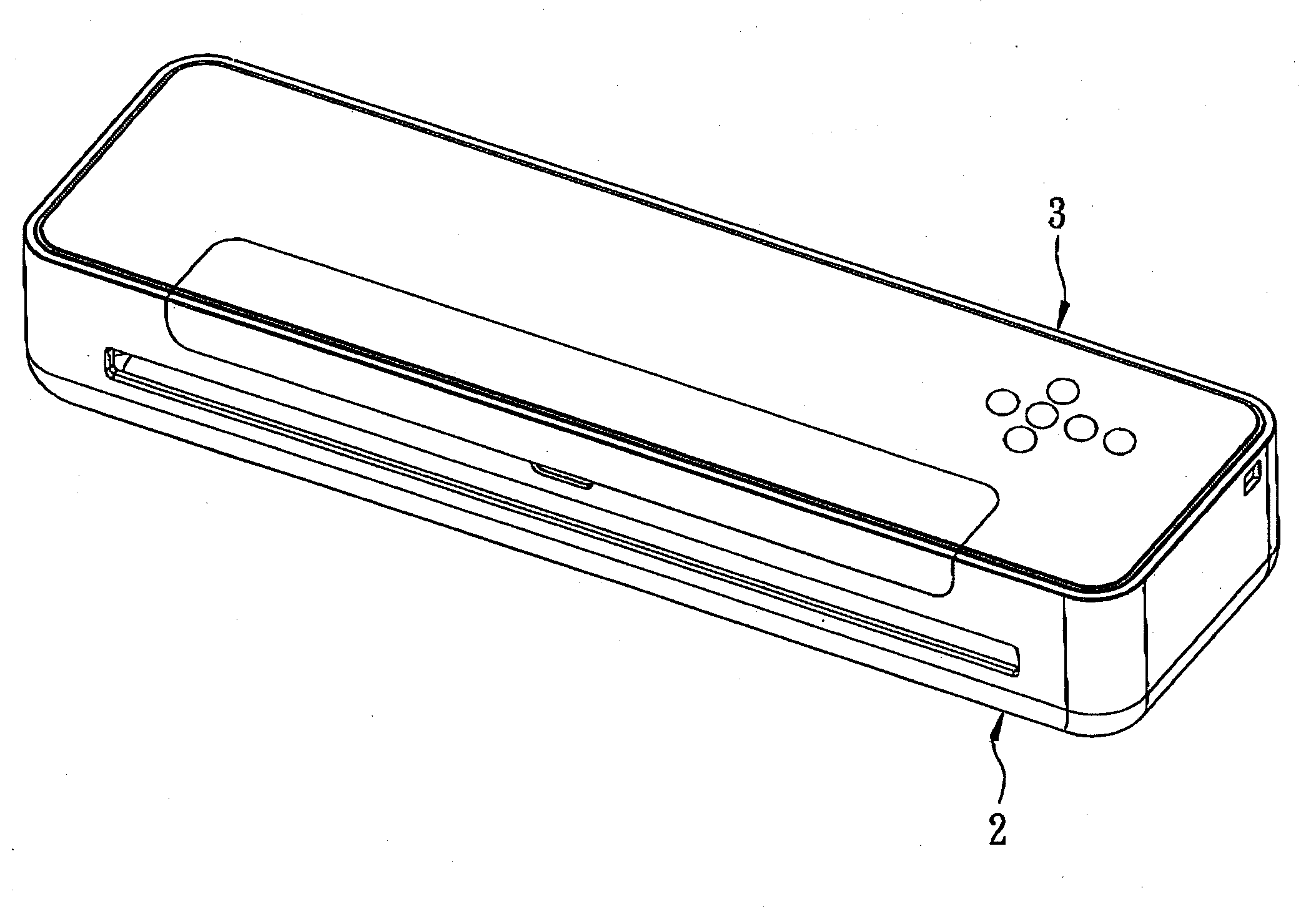
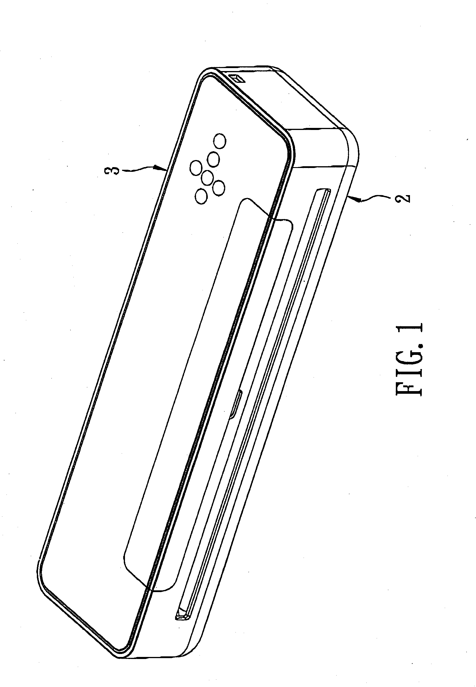
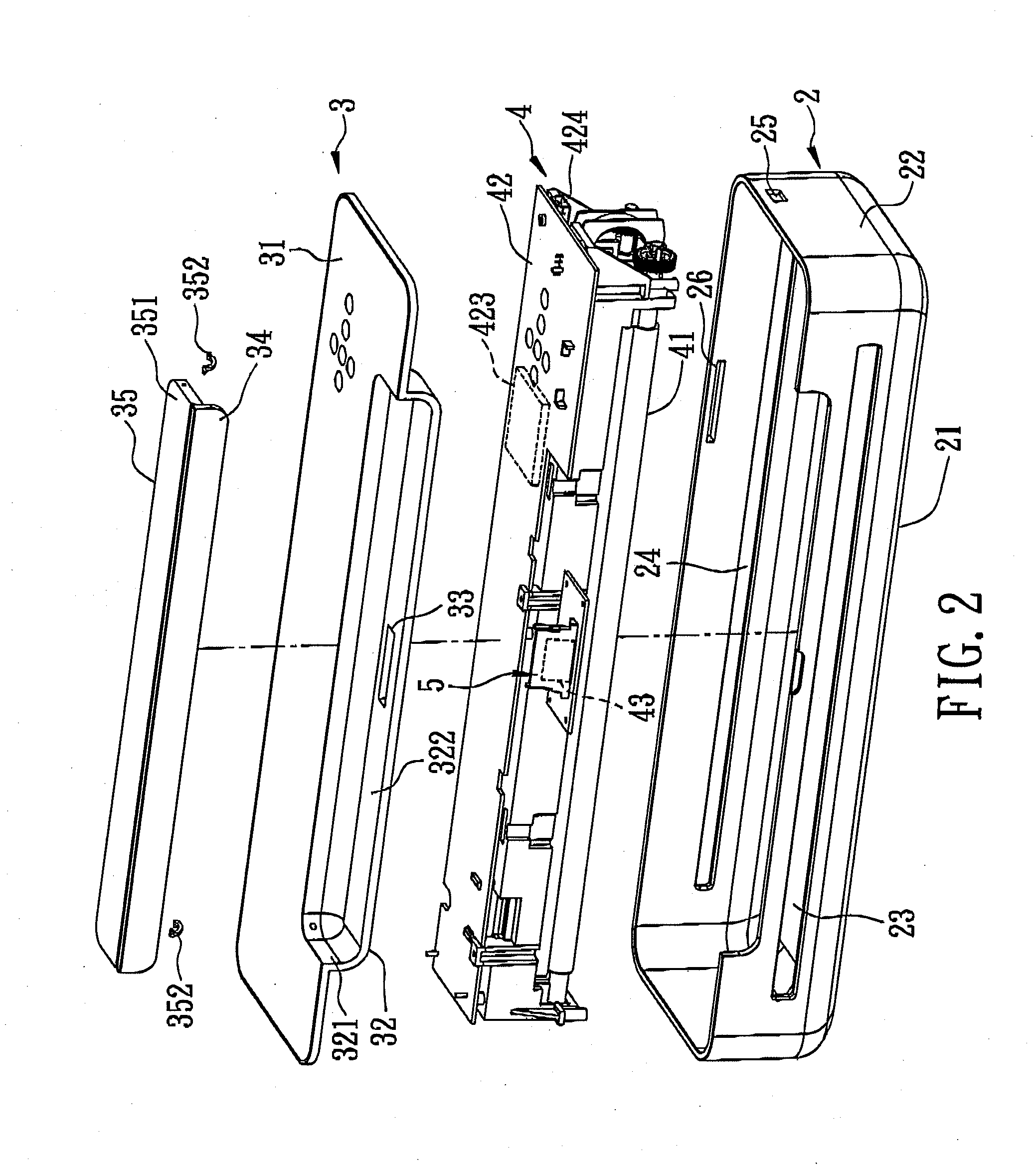
[0037]With reference to FIG. 1, FIG. 2 and FIG. 5, the first preferred embodiment of a scanner according to the present invention is adapted to be directly connected to an electronic device 6 having image display functionality. The electronic device 6 includes a display panel 61, a computing module (not shown) coupled electrically to the display panel 61, and a connecting socket 62 coupled electrically to the computing module. The scanner includes a lower housing 2, an upper housing 3, a scan module 4, and an adaptor 5. In this embodiment, the electronic device 6 is a tablet computer and the display panel 61 is a touch control display panel. However, it should be noted herein that the electronic device 6 may also be a mobile phone or a personal digital assistant (PDA) in other embodiments of the present inventio...


PUM


Abstract

A scanner for an electronic device having image display functionality includes lower and upper housings, a scan unit, and an adaptor. The lower housing is formed on opposite sides with a paper inlet and a paper outlet. The upper housing is mounted on the lower housing, and includes a main body provided with a terminal hole, and a support member disposed proximate to the terminal hole and to abut against the electronic device when the electronic device is connected to the scanner. The scan unit includes a scan module disposed between the lower and upper housings, a control module coupled to the scan module, and a connecting terminal coupled to the control module and accessible via the terminal hole. The adaptor is removably mounted to the connecting terminal so as to permit direct electrical connection between the scanner and the electronic device.

Description

CROSS-REFERENCE TO RELATED APPLICATION [0001]This application claims priority of Chinese Application No. 201110217791.X, filed on Aug. 1, 2011.BACKGROUND OF THE INVENTION [0002]1. Field of the Invention[0003]The invention relates to a scanner, more particularly to a scanner to be connected to an electronic device without requiring a connecting cable or a wire[0004]2. Description of the Related Art[0005]A conventional scanner includes a housing and a scan unit disposed in the housing. The housing has a paper inlet and a paper outlet at opposite sides thereof. The scan unit includes a scan module, a control module coupled electrically to the scan module, and a memory coupled electrically to the control module.[0006]During use, a sheet of to-be-scanned paper enters the scanner through the paper inlet so as to pass through the scan module for conducting an image scan, and exits the scanner through the paper outlet after the image scan is complete. Image data generated as a result of the...

Claims


Application Information

Patent Timeline
IPC IPC(8): H04N1/04
CPCH04N1/00129H04N2201/0081H04N2201/0058
Inventor YU, AN-CHITSAI, KUANG-HUITSENG, SHIH-LUNGCHEN, HUI-ZONG
Owner MUSTEK SYSTEMS
Learn More