

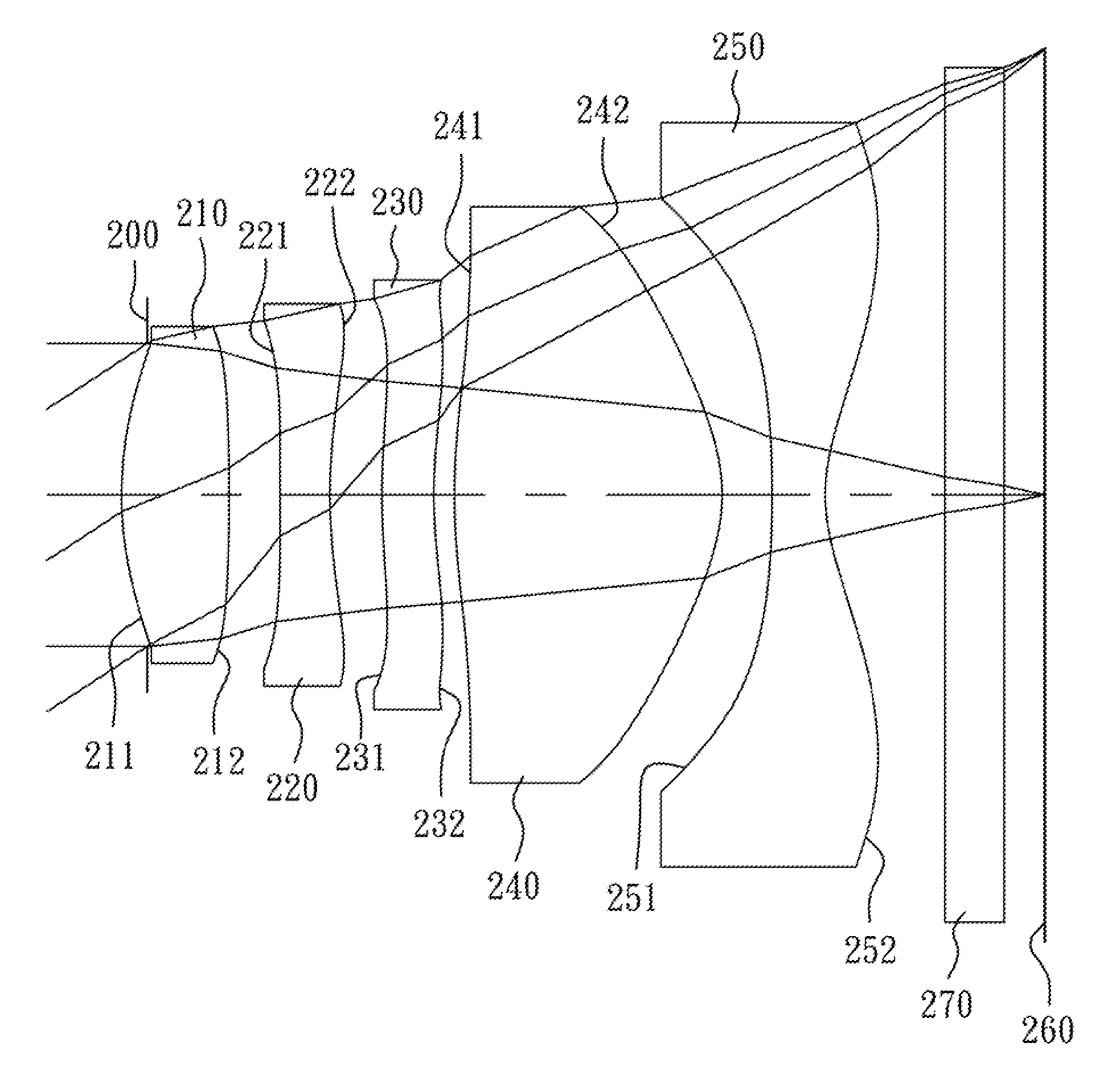
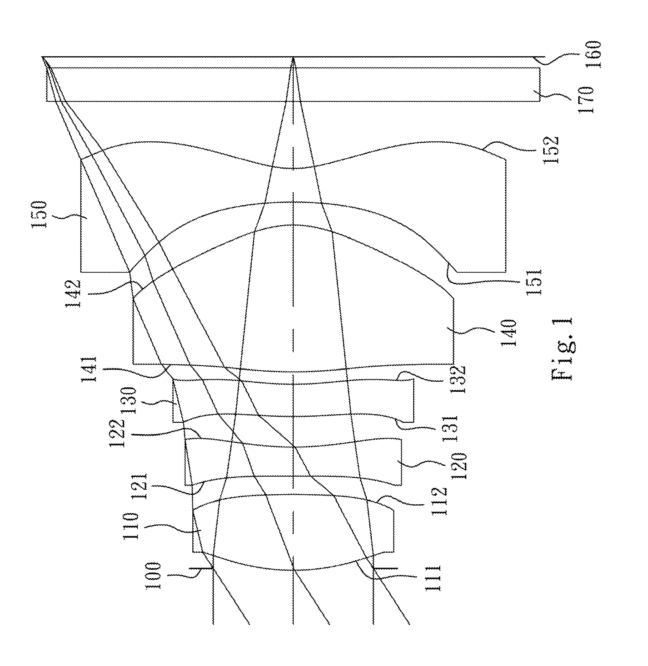
Image capturing optical lens assembly
a technology of optical lens and assembly, applied in the field of can solve the problem that the conventional four-piece lens structure cannot meet the requirements of the compact image capture optical lens assembly
- Summary
- Abstract
- Description
- Claims
- Application Information
AI Technical Summary
Benefits of technology
Problems solved by technology
Method used
Image

Examples
first embodiment
[0063]The equation of the aspheric surface profiles of the aforementioned lens elements of the first embodiment is expressed as the following:
X(Y)=(Y2 / R) / (1+sqrt(1-(1+k)×(Y / R)2))+∑i(Ai)×(Y′)
[0064]where:
[0065]X is the distance of a point on the aspheric surface spaced at a distance Y from the optical axis relative to the tangential plane at the aspheric surface vertex;
[0066]Y is the distance from the point on the curve of the aspheric surface to the optical axis;
[0067]R is the curvature radius of the surface of the lens element;
[0068]k is the conic coefficient; and
[0069]Ai is the i-th aspheric coefficient.
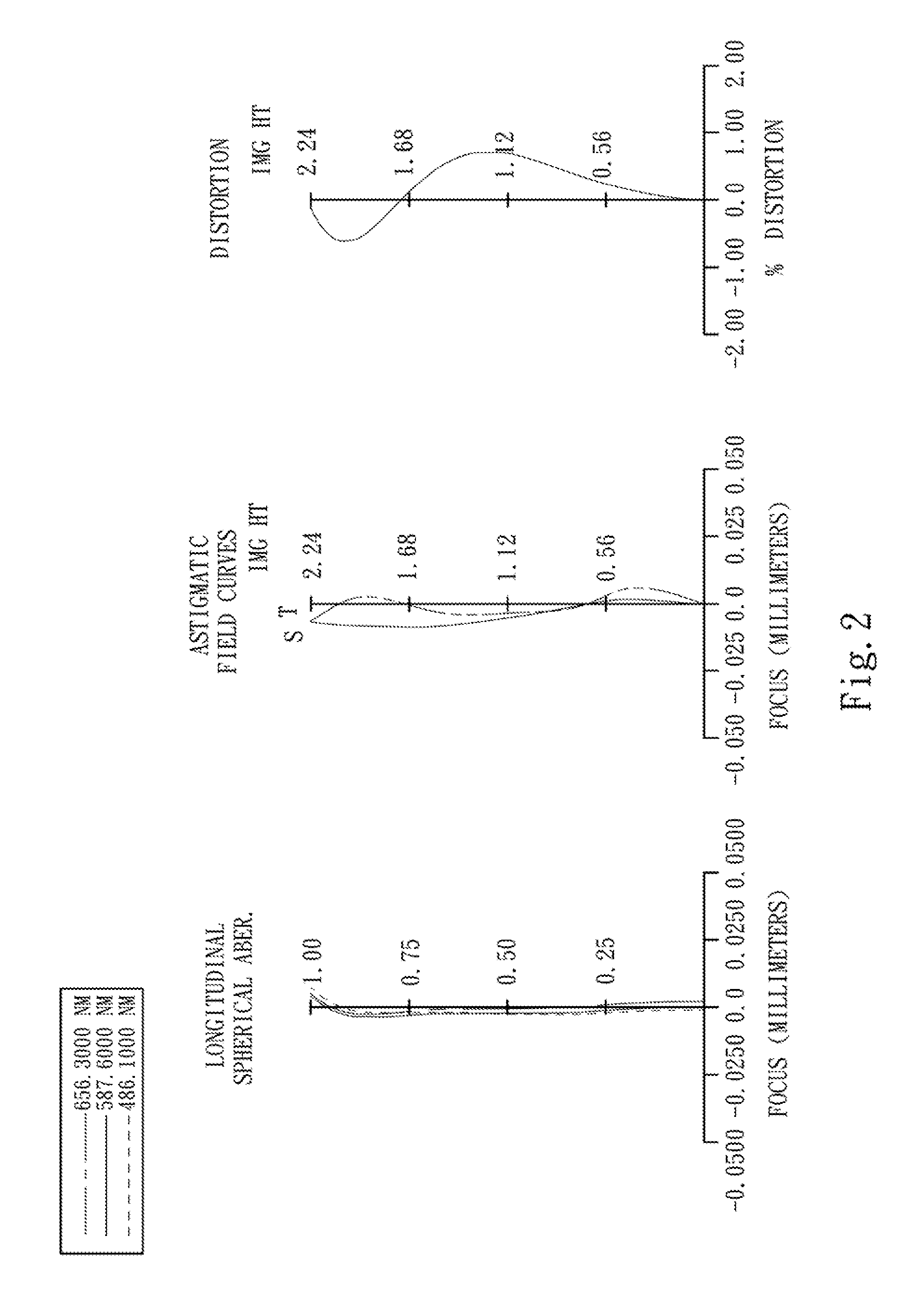
[0070]In the image capturing optical lens assembly according to the first embodiment, when f is a focal length of the image capturing optical lens assembly, Fno is an f-number of the image capturing optical lens assembly, and HFOV is half of the maximal field of view, these parameters have the following values:
[0071]f=3.44 mm;
[0072]Fno=2.40; and
[0073]HFOV=33.1 degrees.
[0074]In the i...
second embodiment
[0088]The detailed optical data of the second embodiment are shown in Table 3 and the aspheric surface data are shown in Table 4 below.
TABLE 32nd Embodimentf = 3.42 mm, Fno = 2.25, HFOV = 33.3 deg.CurvatureFocalSurface #RadiusThicknessMaterialIndexAbbe #length0ObjectPlanoInfinity1Ape. StopPlano−0.1282Lens 11.890050(ASP)0.541Plastic1.54455.93.093−13.716700(ASP)0.2544Lens 2−87.279400(ASP)0.252Plastic1.64023.3−4.2152.785030(ASP)0.2586Lens 33.664800(ASP)0.260Plastic1.64023.3−13.6472.509250(ASP)0.1068Lens 43.282300(ASP)1.342Plastic1.53556.31.469−0.878100(ASP)0.24810Lens 5−5.466200(ASP)0.266Plastic1.53556.3−1.39110.872200(ASP)0.60012IR-FilterPlano0.300Glass1.51764.2—13Plano0.20114ImagePlano—Note:Reference wavelength (d-line) is 587.6 nm.
TABLE 4Aspheric CoefficientsSurface #23456k =−1.01436E+01−2.00000E+01−2.00000E+01−5.31024E+00 2.31008E+00A4 = 1.73069E−01−3.96180E−02−8.89532E−02−5.45072E−02−1.78549E−01A6 =−2.24331E−01−7.53668E−02−1.26097E−01−6.51947E−02−8.76471E−02A8 = 2.17620E−01−3.0009...
third embodiment
[0098]The detailed optical data of the third embodiment are shown in Table 5 and the aspheric surface data are shown in Table 6 below.
TABLE 53rd Embodimentf = 3.41 mm, Fno = 2.00, HFOV = 33.2 deg.FocalSurface #Curvature RadiusThicknessMaterialIndexAbbe #length0ObjectPlanoInfinity1Ape. StopPlano−0.2062Lens 11.767110(ASP)0.497Plastic1.54455.93.60316.127600(ASP)0.1864Lens 24.798200(ASP)0.255Plastic1.64023.3−5.5351.995000(ASP)0.1946Lens 32.643260(ASP)0.266Plastic1.64023.3−9.8371.788090(ASP)0.0958Lens 42.851690(ASP)1.546Plastic1.53556.31.469−0.868420(ASP)0.23610Lens 5−4.756900(ASP)0.285Plastic1.53556.3−1.41110.911080(ASP)0.60012IR-FilterPlano0.300Glass1.51764.2—13Plano0.20714ImagePlano—Note:Reference wavelength (d-line) is 587.6 nm.
TABLE 6Aspheric CoefficientsSurface #23456k =−8.99146E+00−1.00000E+00−1.00000E+00−3.52967E+00 1.96164E+00A4 = 2.07463E−01−2.90378E−02−1.28987E−01−5.30984E−02−1.98194E−01A6 =−1.95226E−01−7.05418E−03−7.93644E−02−7.24302E−02−4.86147E−02A8 = 2.04221E−01−4.38447E−0...
PUM
 Abstract
Description
Claims
Application Information