Articulating ophthalmic surgical probe

a surgical probe and ophthalmology technology, applied in the field of ophthalmological surgical equipment, can solve the problems of large bend radius and large distal tip diameter with significant bend stiffness, trauma to the eye at the incision site, and the articulation mechanism,

Active Publication Date: 2013-02-07
ALCON INC
View PDF11 Cites 133 Cited by
  • Summary
  • Abstract
  • Description
  • Claims
  • Application Information

AI Technical Summary

Benefits of technology

[0008]An articulating optical surgical probe includes a handle sized to fit in a single hand and a single rigid cannula extending from the handle having a diameter of 20 Ga or less. The probe further includes a slotted tip at a distal end of the cannula and at least one optical fiber extending through the handle, the single rigid cannula and the slotted tip, and a pull-wire secured to the slotted tip. When the pull-wire exerts tension on the slotted tip, the slotted tip will deviate from straight to a bend angle controlled by the tension in the pull-wire. The slotted tip is formed from a resilient material that will restore to the straight position when the tension exerted by the pull-wire is released.

Problems solved by technology

This repeated removal and insertion can cause trauma to the eye at the incision site.
The articulation mechanism, however, adds extra complexity and expense.
One flexible laser probe needing no articulation mechanism is commercially available, but this device uses a relatively large diameter optical fiber sheathed in a flexible tube comprising the distal tip, resulting in a large bend radius and large distal tip diameter with significant bend stiffness.
Such a large bend radius, large diameter flexible tube, and straight distal tip causes the useable portion of the fiber to extend a relatively long distance from the distal tip of the probe and limits access of the probe.
A further disadvantage in the known art is the flexibility of the distal cannula, which is a function of the material properties and cross sectional moment of inertia, as determined by the gauge size of the outside diameter of the cannula to fit within the hubbed cannula, and the inside diameter of the cannula to accept the flexible tube.
This flexibility limits the surgeon's ability to use the instrument to manipulate the position of the eye during surgery.
While this probe provides a relatively smaller cross section as compared to the previous probes, such as those disclosed by Scheller et al., it does not provide controllable articulation over a range of angles in the manner those probes do.

Method used


Image

  • Articulating ophthalmic surgical probe
  • Articulating ophthalmic surgical probe
  • Articulating ophthalmic surgical probe

Examples


Embodiment Construction

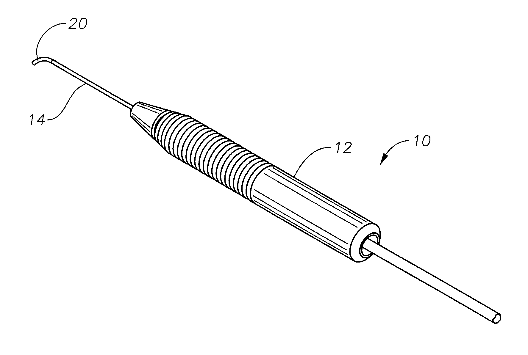
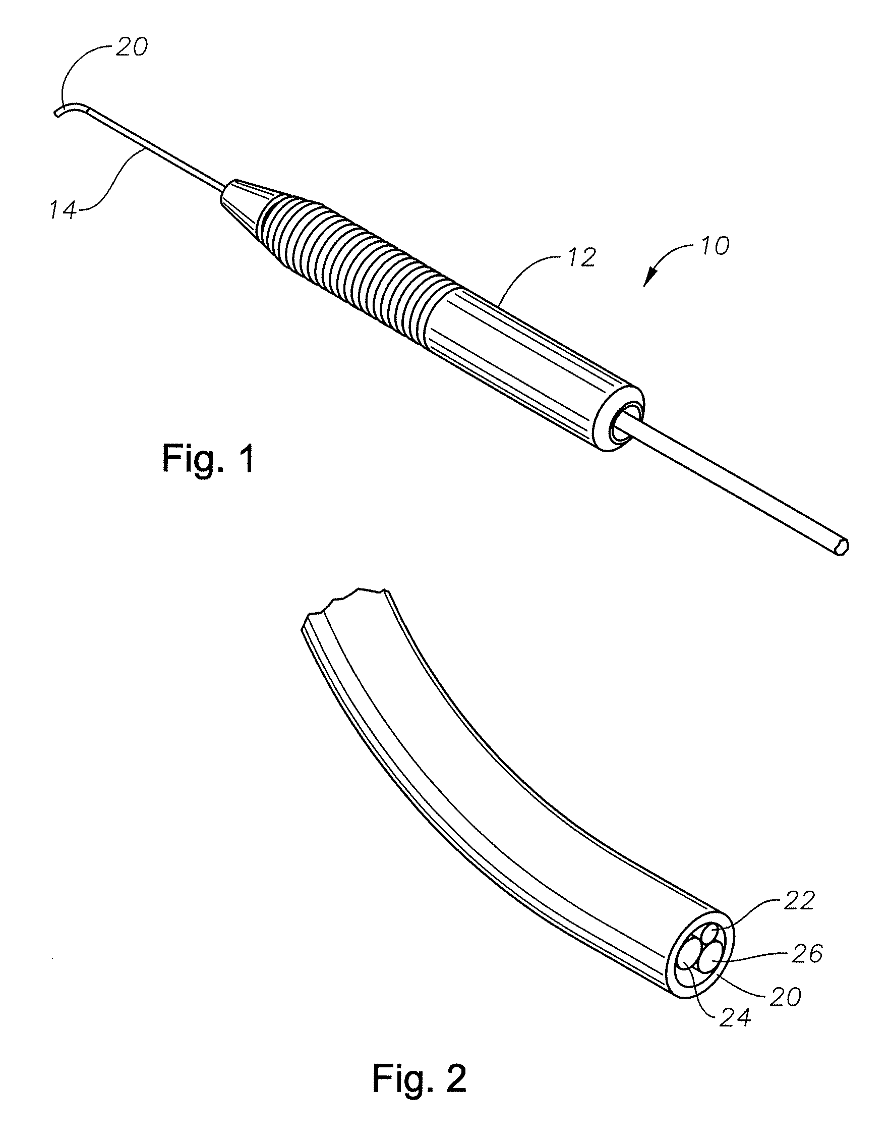
[0014]Various embodiments of the present invention may avoid difficulties associated with previous articulating optical surgical probes. In particular, certain embodiments of the present invention may provide a single rigid cannula with a small diameter not only capable of insertion into very small incisions but also capable of articulating in a controlled fashion through a range of angles. Thus, such embodiments of the present invention combine the advantages of a relatively rigid articulating optical surgical probe with the controllable articulation of dual cannula probes that require a larger diameter.

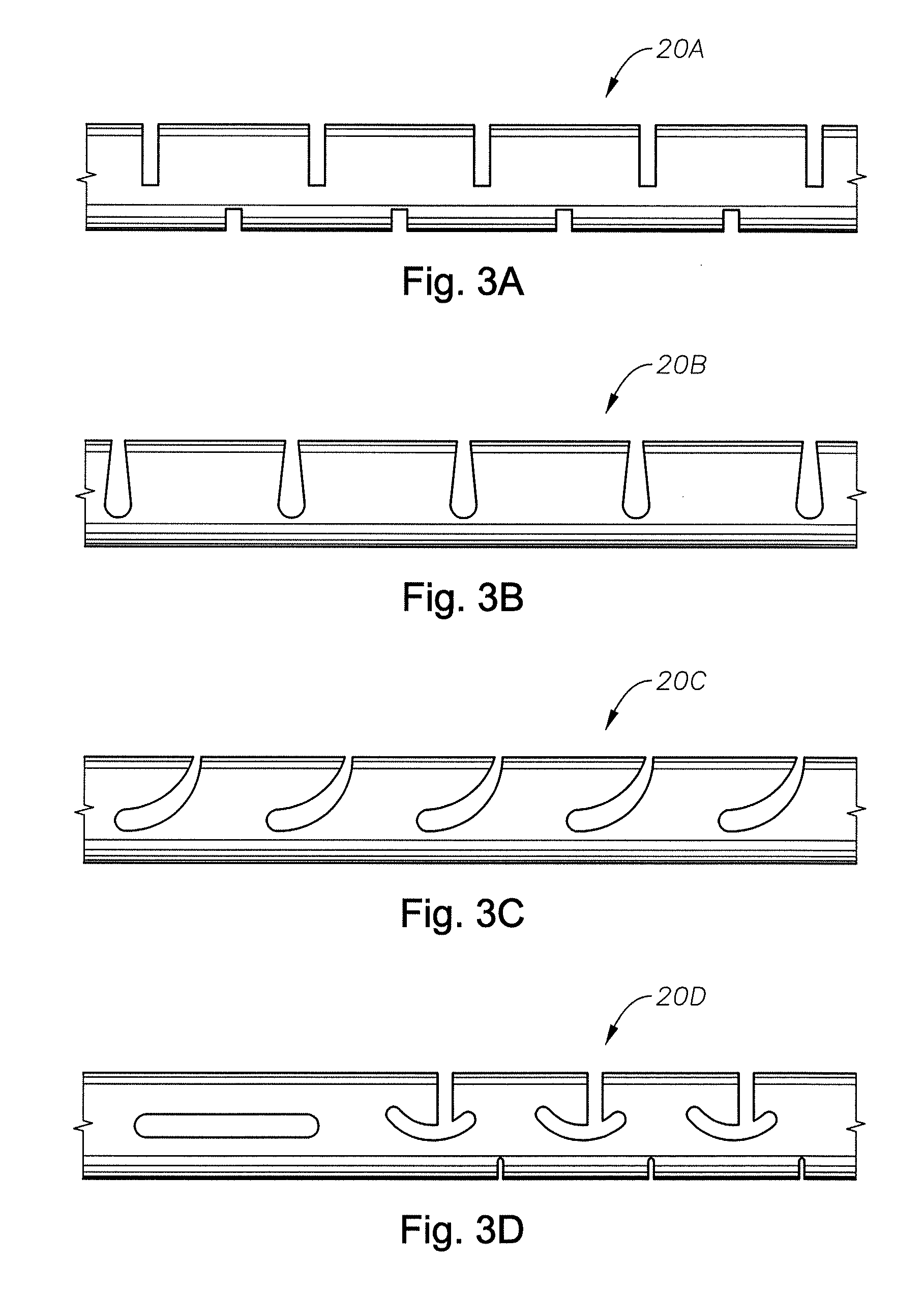
[0015]Particular embodiments of the present invention include a single rigid cannula with a slotted tip of resilient material secured to a pull wire. Tension in the pull wire causes the slotted tip to bend in a particular direction, while releasing the tension allows the resilient tip to restore to its straight position. Pull-wire technology has been used previously to deviate a dis...


PUM


Abstract

An articulating optical surgical probe includes a handle sized to fit in a single hand and a single rigid cannula extending from the handle having a diameter of 20 Ga or less. The probe further includes a slotted tip at a distal end of the cannula and at least one optical fiber extending through the handle, the single rigid cannula and the slotted tip, and a pull-wire secured to the slotted tip. When the pull-wire exerts tension on the slotted tip, the slotted tip will deviate from straight to a bend angle controlled by the tension in the pull-wire. The slotted tip is formed from a resilient material that will restore to the straight position when the tension exerted by the pull-wire is released.

Description

RELATED APPLICATIONS[0001]This application claims priority to U.S. provisional application Ser. No. 61 / 514,751, filed on Aug. 3, 2011, the contents which are incorporated herein by reference.FIELD OF THE INVENTION[0002]This invention relates to ophthalmic surgical equipment and more particularly to posterior segment ophthalmic surgical probes.BACKGROUND OF THE INVENTION[0003]Microsurgical instruments typically are used by surgeons for removal of tissue from delicate and restricted spaces in the human body, particularly in surgery on the eye, and more particularly in procedures for removal of the vitreous body, blood, scar tissue, or the crystalline lens. Such instruments include a control console and a surgical handpiece with which the surgeon dissects and removes the tissue. With respect to posterior segment surgery, the handpiece may be a vitreous cutter probe, a laser probe, or an ultrasonic fragmenter for cutting or fragmenting the tissue and is connected to the control console ...

Claims


Application Information

Patent Timeline
Patent Type & Authority Applications(United States)
IPC IPC(8): A61B1/01A61B1/008
CPCA61B1/00073A61B1/00165A61B1/0052A61F9/00736A61B1/0057A61B1/06A61B1/0055A61B2017/00309A61F9/00
Inventor YU, XIAOYUMCCOLLAM, CHRISTOPHERAULD, JACK
Owner ALCON INC
Why Eureka
Try Eureka