Detachable cryosurgical probe

a cryosurgical and probe technology, applied in the field of cryosurgical probes, can solve the problems of inconvenient use of cryosurgical probes, presently designed cryosurgical probes are not convenient with computerized, ct) applications,

Active Publication Date: 2005-01-13
VARIAN MEDICAL SYSTEMS
View PDF24 Cites 37 Cited by
  • Summary
  • Abstract
  • Description
  • Claims
  • Application Information

AI Technical Summary

Benefits of technology

[0013] During operation fluid is delivered through the fluid delivery / return manifold assembly, through a Joule-Thomson (J-T) port defined at a distal end of the fluid delivery section and is returned through the return manifold section and delivered out of the cryosurgical probe. The insulative vacuum sleeve is provided between the outer sheath and the return manifold section at a control region of the outer sheath proximal to a distally located treatment region of the outer sheath.

Problems solved by technology

There is an inherent problem with this type of system inasmuch as each cryosurgical probe assembly should be used only once due to sterilization and performance factors.
Although cryosurgical probes have been very successfully used for treating prostate cancer their use has been somewhat limited for other applications such as liver, kidney, etc. because of the difficulty of imaging those body parts using ultrasound.
However, presently designed cryosurgical probes are not convenient with, for example, computerized tomography (CT) applications because the probe, including its handle and fluid line connection, are generally disposed along a single direction.
This is problematic given the space considerations present with CT devices.

Method used


Image

  • Detachable cryosurgical probe
  • Detachable cryosurgical probe
  • Detachable cryosurgical probe

Examples


Embodiment Construction

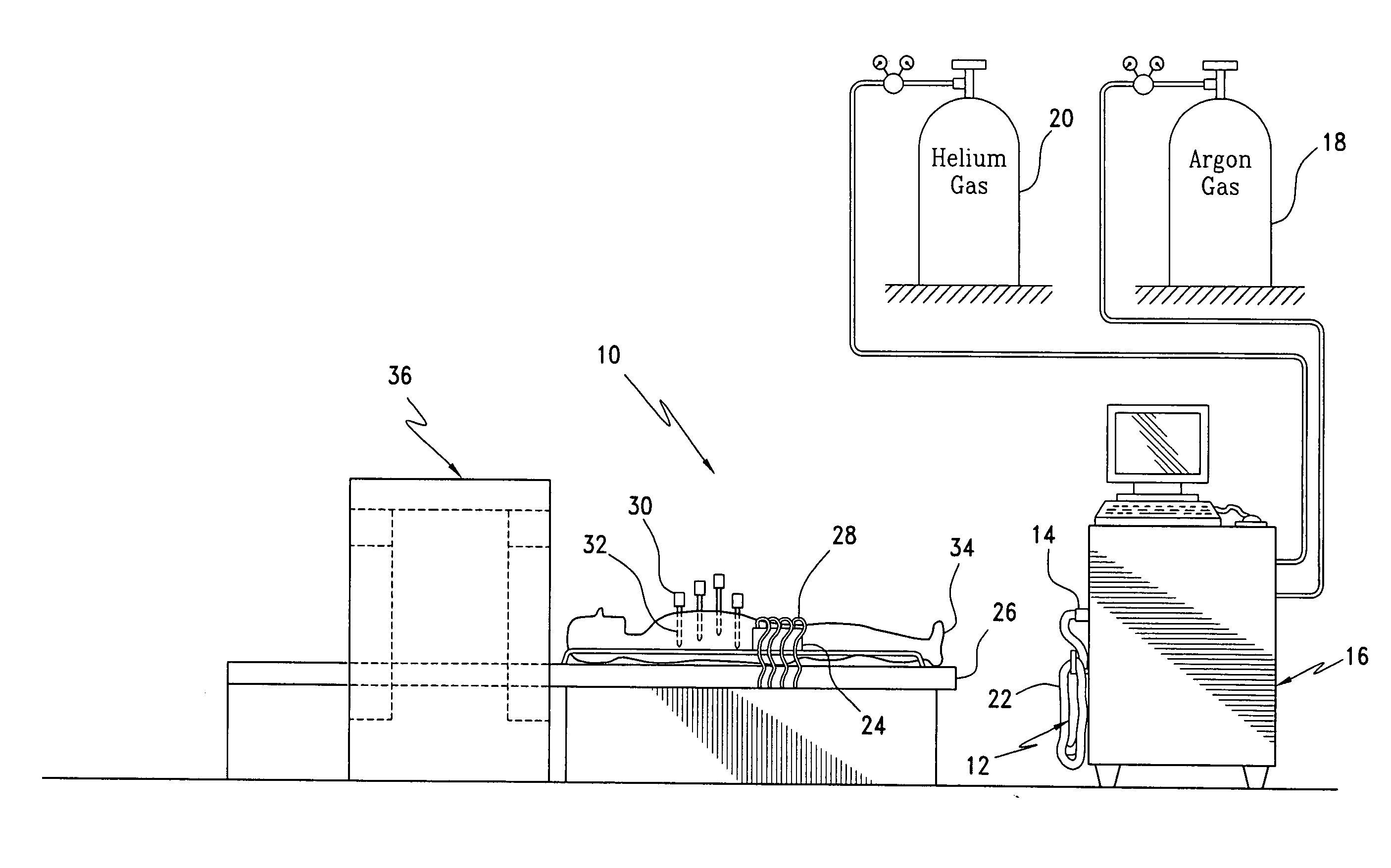
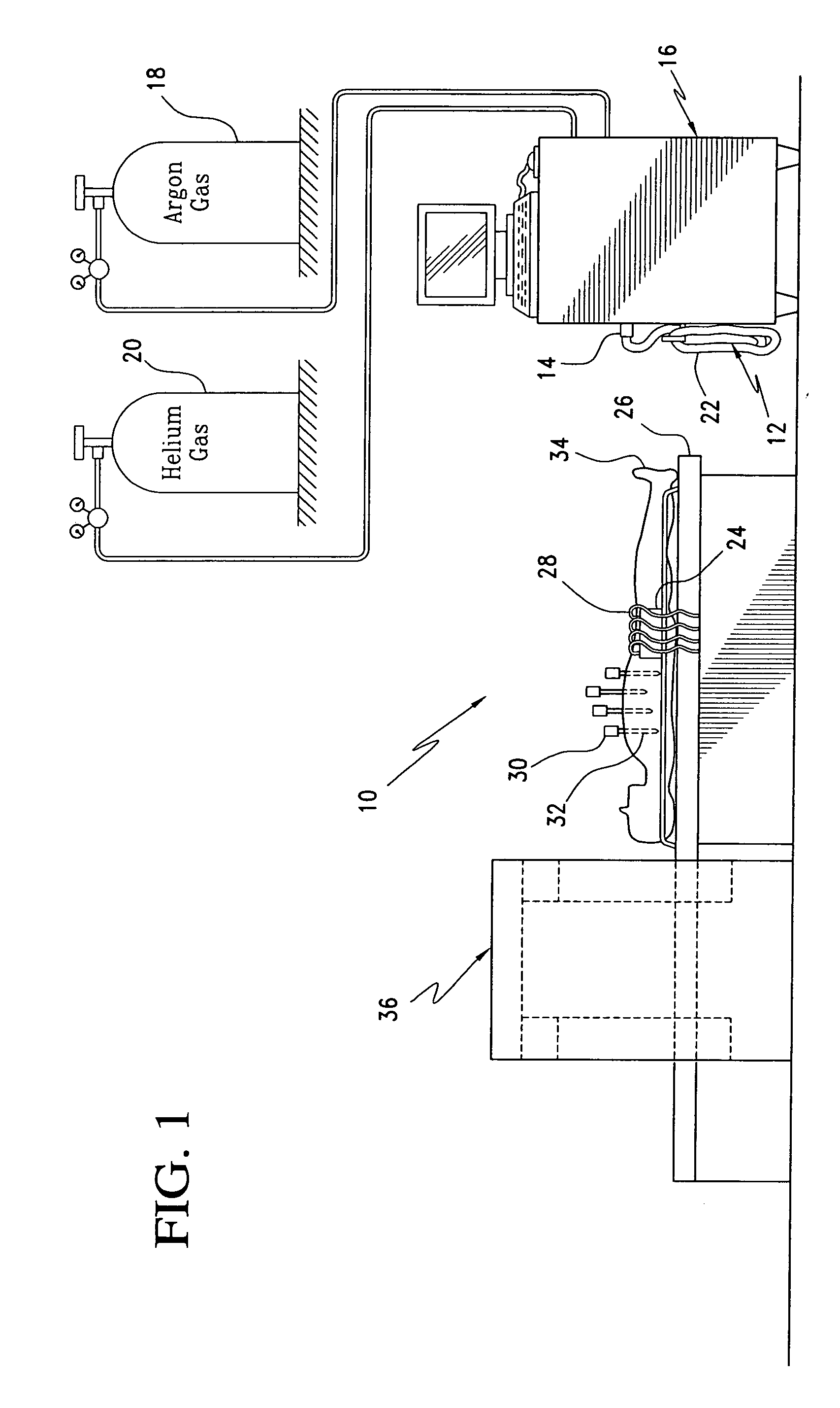
[0035] Referring now to the drawings and the characters of reference marked thereon, FIG. 1 illustrates a preferred embodiment of the cryosurgical probe system of the present invention, designated generally as 10. The cryosurgical probe system 10 includes a fluid supply line 12 that is connected at an inlet section 14 to a source 16 of cryogenic fluid. The fluid source 16 may be, for example, a cryosurgical system such as that manufactured by present assignee, Endocare, Inc., Irvine, Calif. Such a cryosurgical system typically utilizes argon gas from an argon gas source 18 to provide Joule-Thomson cooling of the cryosurgical probes. Alternatively, nitrogen can be used. Alternatively, a fluid supply system can be utilized that does not require an external fluid supply source. Heating of the cryosurgical probes is typically provided by a helium gas source 20 for providing a helium gas flow through the Joule-Thomson nozzle of the cryosurgical probe. This provides a heating effect. Such...


PUM


Abstract

A cryosurgical probe system includes a fluid supply line connectable at an inlet section to a source of cryogenic fluid; a fluid connector assembly securely connected to an outlet section of the fluid supply line for receiving fluid from the outlet section of the fluid supply line; and, a detachable cryosurgical probe detachably connectable to the fluid connector assembly. The cryosurgical probe system includes the capability of providing return fluid flow.

Description

CROSS REFERENCE TO RELATED APPLICATIONS [0001] This is a continuation-in-part of U.S. Ser. No. 10 / 603,883, entitled Detachable Cryosurgical Probe, filed Jun. 25, 2003.BACKGROUND OF THE INVENTION 1. Field of the Invention [0002] The present invention relates to cryosurgical probes and more particularly to a detachable cryosurgical probe. 2. Description of the Related Art [0003] Cryosurgery involving the use of a cryosurgical probe assemblies typically involves the use of cryoprobes that are each attached to a handle that are, in turn, connected to a high-pressure fluid line with a quick-disconnect for attachment to a fluid source. There is an inherent problem with this type of system inasmuch as each cryosurgical probe assembly should be used only once due to sterilization and performance factors. Therefore, typically, the entire cryosurgical probe assembly and high-pressure fluid line must be discarded after that single use. Due to these sterilization / performance requirements there ...

Claims


Application Information

Patent Timeline
Patent Type & Authority Applications(United States)
IPC IPC(8): A61B17/00A61B18/02F25B9/02F28D7/10
CPCA61B18/02A61B2017/0046A61B2018/00041F28F2255/18A61B2018/0293F25B9/02F28D7/106A61B2018/0262
Inventor DAMASCO, SANFORD D.DUONG, THACH
Owner VARIAN MEDICAL SYSTEMS
Why Eureka
Try Eureka