
Multi-spot laser surgical probe using faceted optical elements

a laser surgical probe and optical element technology, applied in the field of optical surgical probes, can solve the problems of destroying the spot pattern, difficult to produce diffractive elements, and high cost of diffractive elements

Inactive Publication Date: 2013-02-14
ALCON RES LTD
View PDF11 Cites 38 Cited by
  • Summary
  • Abstract
  • Description
  • Claims
  • Application Information

AI Technical Summary

Benefits of technology

The present invention provides a thermally robust optical surgical probe with a multi-spot generator. The probe includes a handpiece and a cannula with a faceted optical adhesive element. The light guide is positioned in the handpiece to carry the light beam to the cannula. A high-conductivity ferrule may be used at the distal end of the light guide. The cannula may be made of transparent material. The technical effect of this invention is to improve the precision and safety of optical surgical procedures.

Problems solved by technology

Difficulties can arise in the use of a diffractive beam splitter element at a distal end of the optical surgical probe.
For example, if the diffractive beam splitter element is placed into a medium other than air, such as saline solution or oil, the recessed portions of the microscopic surface relief structure of the diffractive beam splitter element can be filled with material having a different refractive index than air, which can ruin the spot pattern.
As yet another example, the spacing between the spots can vary for different wavelengths, which can be problematic when an aiming beam is of a certain color while a treatment beam is of a different color.
Lastly, diffractive elements are frequently expensive and difficult to produce, and this is particularly the case when the diffractive element must be constructed to fit into a small area, such as a distal tip of a surgical probe for surgical instruments that are 23-gauge or smaller.

Method used


Image

  • Multi-spot laser surgical probe using faceted optical elements
  • Multi-spot laser surgical probe using faceted optical elements

Examples


Embodiment Construction

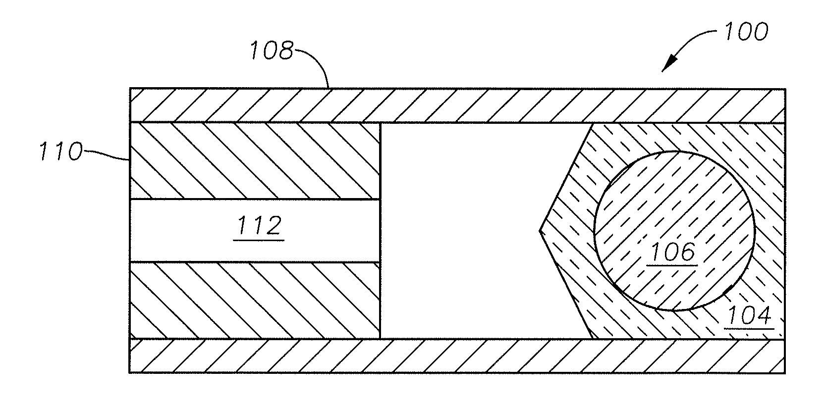
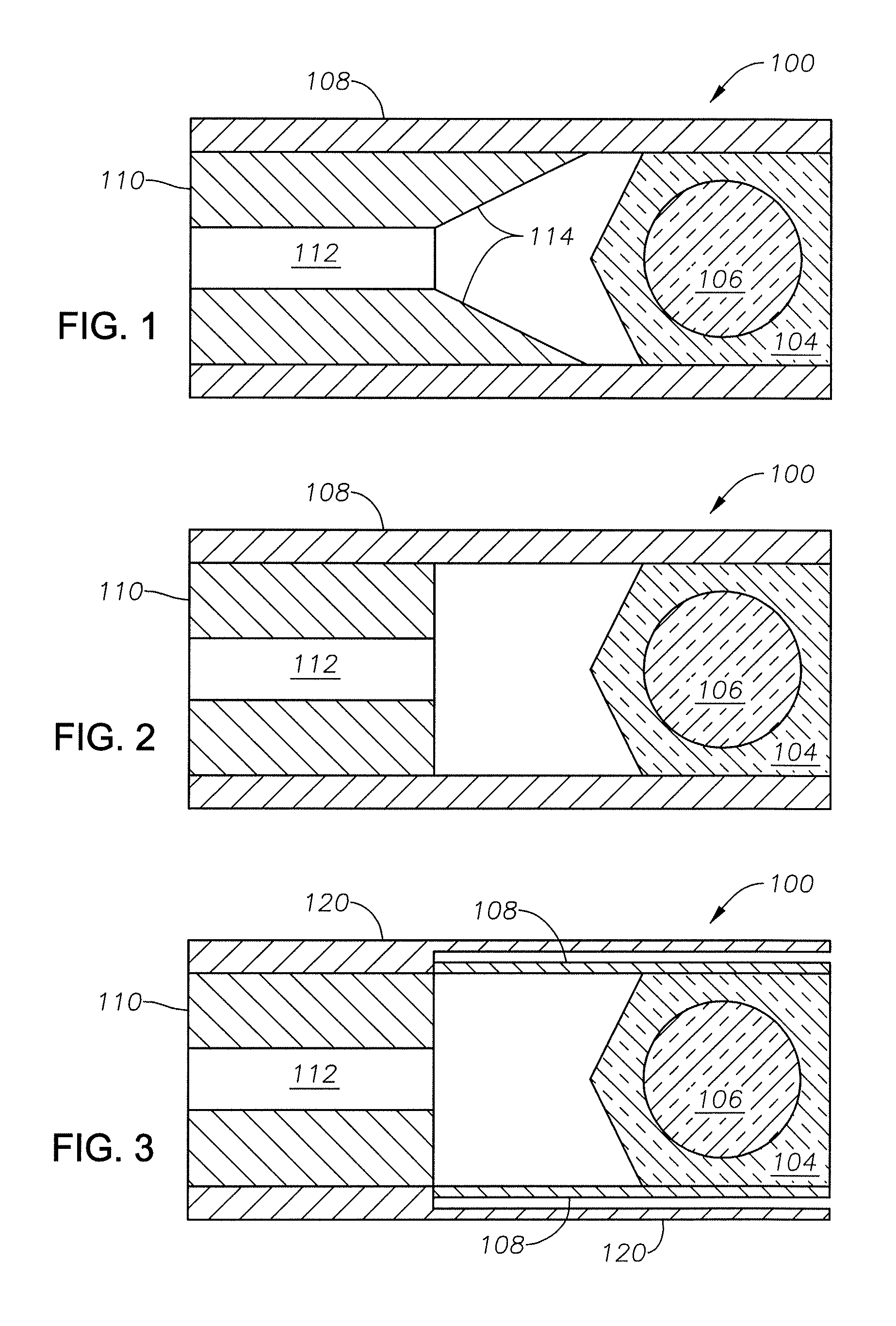
[0010]Co-pending U.S. application Ser. No. 12 / 959,533, filed on Dec. 3, 2010 and commonly assigned with the present Application, describes a multi-spot optical surgical probe using faceted optical adhesive. Various embodiments of the present invention provide additional features to facilitate the use of faceted optical adhesive in optical surgical probes. In particular, certain embodiments of the present invention provide a thermally robust optical surgical probe using faceted optical adhesive. As described in detail below, particular embodiments of the present invention incorporate o additional features to reduce the likelihood that “hot spots” will develop in the surgical probe that could cause the faceted optical adhesive or the adhesive joining the ferrule and the cannula to degrade and / or fail.

[0011]In certain embodiments of the present invention, a ferrule located within the distal end of the probe is modified to improve its ability to conduct heat away from the distal tip of ...


PUM


Abstract

In particular embodiments of the present invention, an optical surgical probe includes a handpiece configured to optically couple to a light source and a cannula at a distal end of the handpiece. The probe further includes at least one light guide within the handpiece. The light guide is configured to carry a light beam from the light source to a distal end of the handpiece. The probe also includes a multi-spot generator in the cannula that includes a faceted optical adhesive with a faceted end surface spaced from a distal end of the light guide. The faceted end surface includes at least one facet oblique to a path of the light beam. In some embodiments, the probe also includes a high-conductivity ferrule at the distal end of the light guide. In other embodiments, the cannula is formed from a transparent material.

Description

RELATED APPLICATIONS[0001]This application claims priority to U.S. provisional application Ser. No. 61 / 521,447, filed on Aug. 9, 2011, the contents which are incorporated herein by reference. This application is related to co-pending U.S. patent application Ser. No. 12 / 959,533, filed on Dec. 3, 2010, and commonly assigned with the present Application.FIELD OF THE INVENTION[0002]This invention relates to optical surgical probes and, more particularly, to a multi-spot laser surgical probe using faceted optical elements.BACKGROUND OF THE INVENTION[0003]Optical surgical probes deliver light to a surgical field for a variety of applications. In some applications, it may be useful to deliver light to multiple spots in the surgical field. For example, in pan-retinal photocoagulation of retinal tissue, it may be desirable to deliver laser light to multiple spots so as to reduce the time of the pan-retinal photocoagulation procedure. Various techniques have been employed to produce multiple ...

Claims


Application Information

Patent Timeline
IPC IPC(8): A61B18/20
CPCA61B1/00066A61B1/07A61B1/128A61B1/00096A61B2018/0091A61B2018/2277A61F2009/00863A61B18/201A61F9/00821A61B18/20
Inventor SMITH, RONALD T.ZICA, MICHAEL ARTHURBOUCH, DUSTIN JACOB
Owner ALCON RES LTD
Learn More