
Method and apparatus for debugging programs

a software program and program technology, applied in the field of debugging programs, can solve the problems of inability to detect bugs, high cost of not discovering bugs, and injury of a person relying on the designated behavior of the computerized device, and achieve the effect of faster and more efficien

Active Publication Date: 2013-02-07
GEIST DANIEL
View PDF2 Cites 131 Cited by
  • Summary
  • Abstract
  • Description
  • Claims
  • Application Information

AI Technical Summary

Benefits of technology

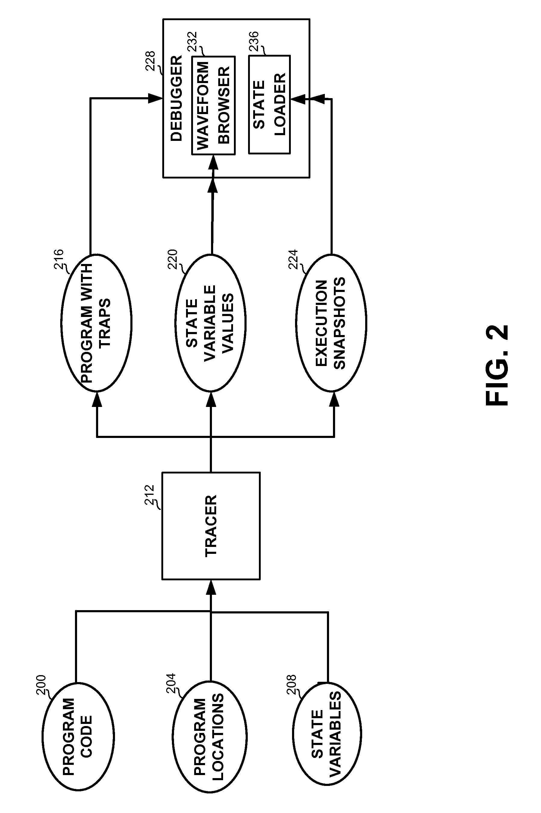
This patent describes a method for debugging computer programs by displaying a graphic waveform of state variables and allowing the user to select specific points in time to resume the program's execution. The method can also involve receiving program locations and state variables, executing the program, and storing the state variables when the program reaches specific points in code. This allows for easier understanding and analysis of the program's behavior and can lead to improved efficiency in debugging. The patent also includes a computer program product with corresponding instructions for displaying the waveform and resuming the program's execution.

Problems solved by technology

However, computerized devices are bug-prone, and thus require a testing phase in which the bugs should be discovered.
The cost of not discovering a bug may be enormous, as the consequences of the bug may be disastrous.
For example, a bug may cause the injury of a person relying on the designated behavior of the computerized device, such as a medical device, a traffic light, or others.
Additionally, a bug in a marketed product may be expensive to fix, as patching it may require call-back of devices from the market.
Hence, many developers of computerized devices invest a substantial portion of the development cycle in discovering erroneous behaviors of the computerized device.
The testing phase is considered one of the most difficult tasks in designing a computerized device.
Debugging is one of the most time consuming tasks of a software developer.
Finding bugs and determining their root cause may require significant human and time resources.
It is often the case that bugs exhibit unexpected behavior only a long time and many instructions after it was created, which makes discovering it much harder.
Generally, as the software is more complex, debugging may take more time and may be more complex and involve more data.
Debugging may become especially difficult when the software contains some form of parallel processing, for example software utilizing multiple threads, multiple processors, or the like.

Method used


Image

  • Method and apparatus for debugging programs
  • Method and apparatus for debugging programs
  • Method and apparatus for debugging programs

Examples


Embodiment Construction

[0015]The disclosed subject matter is described below with reference to flowchart illustrations and / or block diagrams of methods, apparatus (systems) and computer program products according to embodiments of the subject matter. It will be understood that blocks of the flowchart illustrations and / or block diagrams, and combinations of blocks in the flowchart illustrations and / or block diagrams, can be implemented by computer program instructions. These computer program instructions may be provided to one or more processors of a general purpose computer, special purpose computer, a tested processor, or other programmable data processing apparatus to produce a machine, such that the instructions, which execute via the processor of the computer or other programmable data processing apparatus, create means for implementing the functions / acts specified in the flowchart and / or block or blocks of block diagrams.

[0016]These computer program instructions may also be stored in a non-transient ...


PUM


Abstract

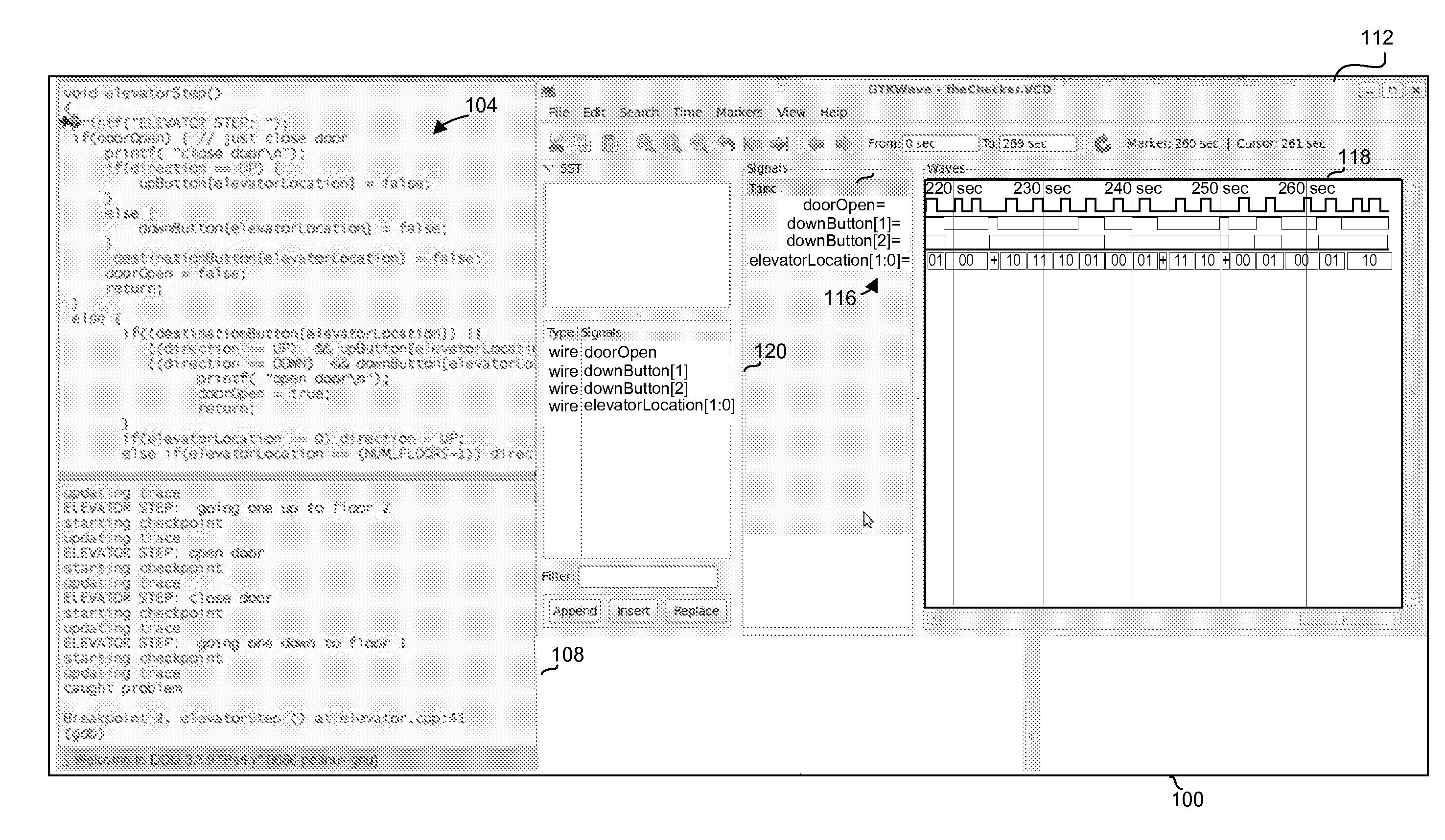
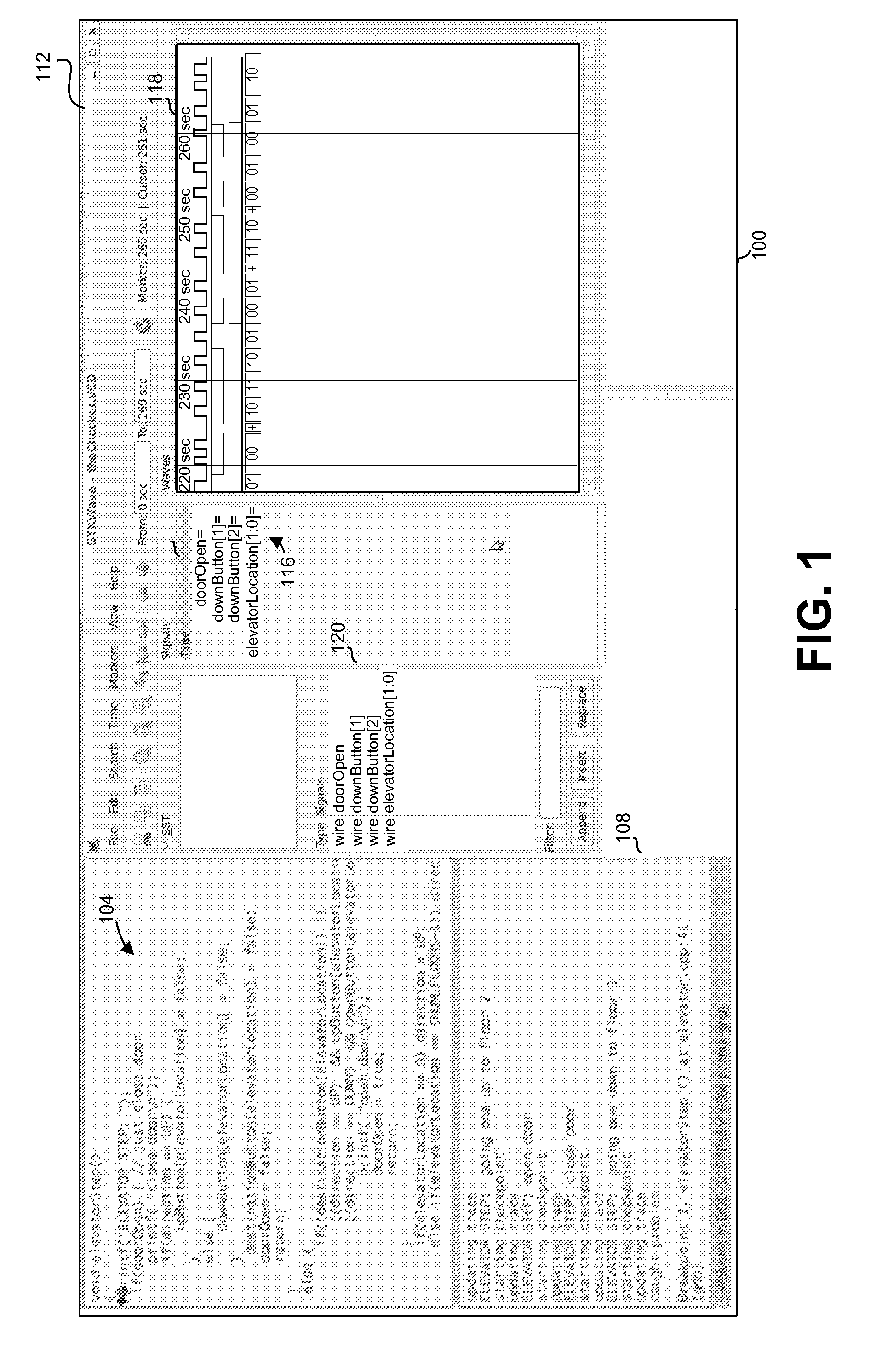
A computer-implemented method, apparatus and computer program product for debugging programs, the method comprising: displaying a graphic waveform showing values of one or more state variables of a computer program being debugged in two or more points in time; receiving a user selection from points in time, of an indication to a selected point in time in execution from the graphic waveform; and resuming within a debugger an execution state of the computer program associated with the selected point in time.

Description

CROSS-REFERENCE TO RELATED APPLICATIONS[0001]This application claims the benefit of U.S. Provisional Application No. 61 / 514,533 filed Aug. 3, 2011, which is hereby incorporated by reference in its entirety.TECHNICAL FIELD[0002]The present disclosure relates to debugging programs in general, and to techniques and user interfaces for debugging software programs, in particular.BACKGROUND[0003]Computerized devices control almost every aspect of our life—from writing documents to controlling traffic lights. However, computerized devices are bug-prone, and thus require a testing phase in which the bugs should be discovered. The cost of not discovering a bug may be enormous, as the consequences of the bug may be disastrous. For example, a bug may cause the injury of a person relying on the designated behavior of the computerized device, such as a medical device, a traffic light, or others. Additionally, a bug in a marketed product may be expensive to fix, as patching it may require call-ba...

Claims


Application Information

Patent Timeline
Patent Type & Authority Applications(United States)
IPC IPC(8): G06F11/36
CPCG06F11/3636G06F11/323G06F11/3664G06F11/366G06F11/362
Inventor GEIST, DANIEL
Owner GEIST DANIEL
Learn More