
Flexible display with display support

a display and support technology, applied in the direction of identification means, instruments, ways, etc., can solve the problems of unsupported parts of the display, add mechanical complexity, and non-uniform radius of the display, and achieve the effect of facilitating the movement of the display

Active Publication Date: 2013-02-14
SAMSUNG ELECTRONICS CO LTD
View PDF2 Cites 185 Cited by
  • Summary
  • Abstract
  • Description
  • Claims
  • Application Information

AI Technical Summary

Benefits of technology

This patent describes a display system with a flexible display that can be stored and opened. The system includes a support frame with two main supports that can be opened and closed. There is a space between the main supports to allow for partial curving of the display without interfering with the supports. An additional display support is positioned to support the curved part of the display, ensuring it can be opened without damaging the display. The technical effect of this invention is to provide a display system with a flexible display that can be securely stored and opened without compromising its lifespan.

Problems solved by technology

For larger displays compared to the device body more turns are required, which adds mechanical complexity.
There are a lot of possibilities to realize the movement of the display with respect to the display system, but most of them result in unsupported parts of the display.
Another reason is that even in a mono-layer display (which is by definition impossible) internal tensions caused by the thickness and opposing forces of the material will cause a non-uniform radius in the display.
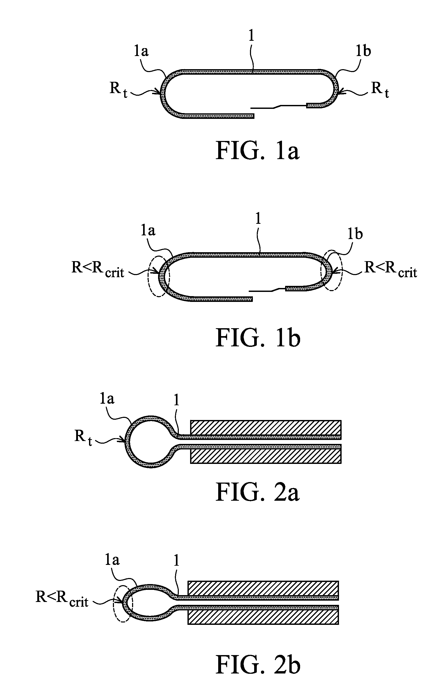
As mentioned before this deviance from the ideal circular shape results locally in smaller radii than specified for a flexible display.
Due to the compressive strain, the layers at the inside of the curve might form a buckle (see 1c) leading to display failure.
On the other hand, the tensile strain in the layers on the outside of the curve can lead to cracks in these layers leading to display failure or a sharply reduced lifetime (in case a water barrier cracks).

Method used


Image

  • Flexible display with display support
  • Flexible display with display support
  • Flexible display with display support

Examples


Embodiment Construction

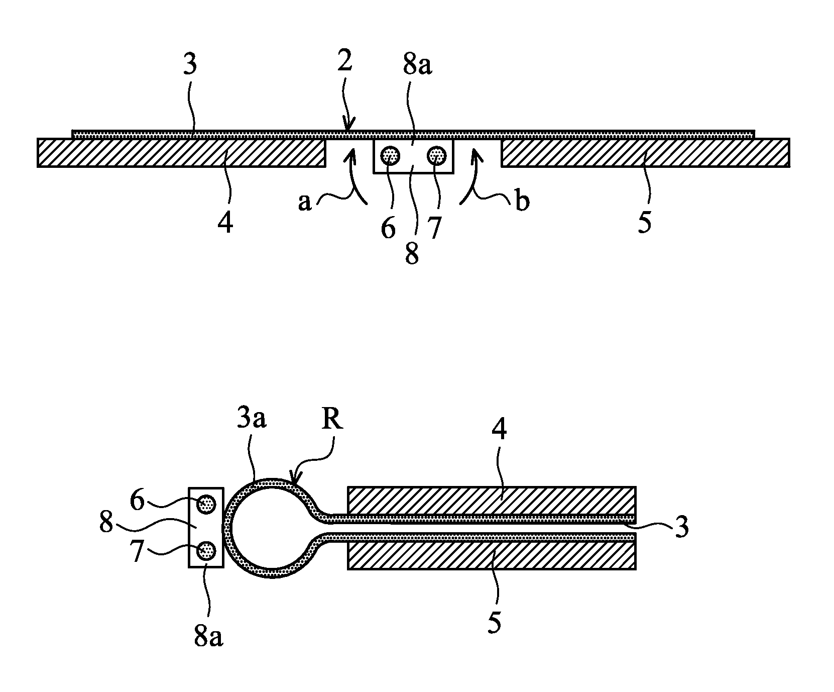
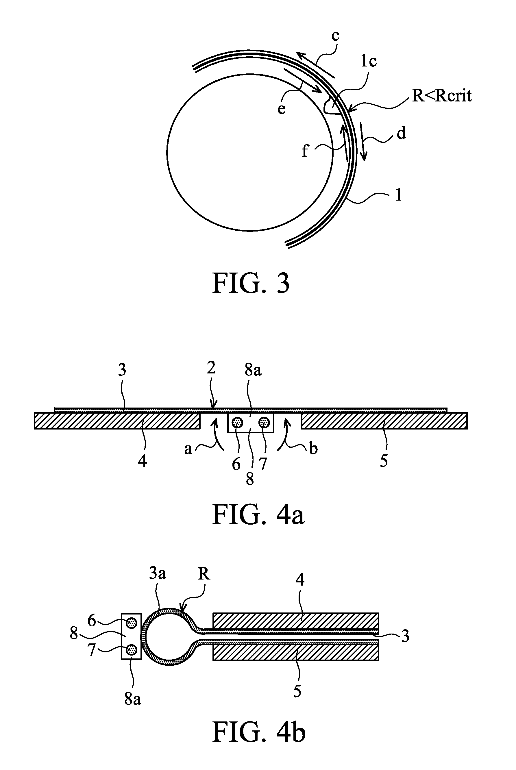
[0025]A display system 2 schematically shown in FIGS. 4A and 4B and in perspective view (but without display) in FIG. 4C is a ‘book’ embodiment as described by applicant's Provisional Application Ser. No. 61 / 506,177, filed on Jul. 11, 2011, which is hereby incorporated by reference. It comprises a flexible display 3 and a display support frame comprising two main display supports 4, 5. These supports are connected via hinges 6, 7 located in a hinge part and are each structurally configured to support a respective portion of the flexible display 3. The hinge part is also working as an additional display support 8. The two main display supports 4, 5 are rotatable in the direction of arrows a, b between a configuration shown in FIG. 4A for fixing the flexible display in a planar configuration to a closed storage position shown in FIG. 4B. In the open position the gap created by the hinges 6, 7 between the main supports 4, 5 is closed for a major part by the display support 8 and substa...


PUM


Abstract

A display system includes a continuous flexible display, two main display supports each structurally configured to support a respective portion of the flexible display, a segment of the flexible display being located between the said respective display portions. The two main display supports are hingeable between a closed configuration for fixing the flexible display in a storage position and an open configuration for fixing the flexible display in an open position. In the storage position between the main display supports there is a free space enabling a partial curvature of said display segment without conflicting with the respective main display support. At least one additional display support is configured to support said segment of the flexible display in the storage position and facilitates the curvature of the display segment with a predefined radius which is larger than the critical radius Rcrit for the flexible display.

Description

[0001]This application claims the benefit of U.S. Provisional Application Ser. No. 61 / 506,180, filed on Jul. 11, 2011, which is hereby incorporated by reference.TECHNICAL FIELD [0002]The present invention generally relates to flexible displays. The present invention specifically relates to flexible displays provided with display supports.DESCRIPTION OF RELATED ART [0003]Flexible and especially rollable displays are manufactured on an organic substrate and are very thin. This makes it possible to repeatedly bend them with a small radius, a requirement for a rollable display. The advantages of a rollable display are the small volume needed for storing in the closed position and the lack of glass making the display unbreakable and of light weight.[0004]A number of product concepts have been developed for flexible displays. The present invention focuses on the ‘book’ and the ‘wrap’ concept. A ‘wrap’ concept is shown in WO 2008 / 054206 A2.[0005]The ‘book’ concept is the simplest implement...

Claims


Application Information

Patent Timeline
Patent Type & Authority Applications(United States)
IPC IPC(8): G09F7/00
CPCG06F1/1652G09F9/301H04M1/0268H04M1/0216H04M1/022E01F9/688
Inventor VERSCHOOR, VOLKER BARNHARTVAN DIJK, ROBERT SJANG JOSINEWALTERS, MICHAEL JOHANNES ANNA MARIAVAN DEN TILLAAR, JOHANNES HERMANUSHAMERS, JOHANNES CORNELIS ADRIAANVAN LIESHOUT, PETRUS JOHANNES GERARDUS
Owner SAMSUNG ELECTRONICS CO LTD
Learn More