
Dripfree gasoline nozzle

Inactive Publication Date: 2013-02-14
MILLARD MATTHEW DAVID
View PDF5 Cites 22 Cited by
  • Summary
  • Abstract
  • Description
  • Claims
  • Application Information

AI Technical Summary

Benefits of technology

The patent is about a device that reduces drops from a nozzle. It includes a valve body with a frusto-conical outer surface, a first aperture for a movable valve closure mechanism, and additional apertures for fluid flow. There is also a spring biased valve closure mechanism with a stem and a frusto-conical valve head that seals with the outer surface of the valve body. The valve head also has an annular groove for an o-ring. The device can be fitted at the end of a gasoline nozzle or affixed there.

Problems solved by technology

The problem of reducing or eliminating fuel loss related to dripping from gasoline dispenser nozzles has long been recognized, but a cost effective system and method for eliminating drips has proven elusive.
Vehicle refueling using existing gasoline nozzle designs results in gasoline vapor and spillage losses through drips from the nozzle, particularly after nozzle shutoff as the device is removed from the fueling port.
Existing systems for reducing or eliminating fuel drips are mechanically complex, fail to provide a universal solution that can be applied as a retrofit or incorporated into a wide range of commercially available nozzles, are not physically robust, and / or have proven to be costly to adopt.

Method used


Image

  • Dripfree gasoline nozzle
  • Dripfree gasoline nozzle
  • Dripfree gasoline nozzle

Examples


Embodiment Construction

[0016]The following description is presented to enable any person skilled in the art to make and use the invention. For purposes of explanation, specific nomenclature is set forth to provide a thorough understanding of the present invention. Descriptions of specific embodiments or applications are provided only as examples. Various modifications to the embodiments will be readily apparent to those skilled in the art, and general principles defined herein may be applied to other embodiments and applications without departing from the spirit and scope of the invention. Thus, the present invention is not intended to be limited to the embodiments shown, but is to be accorded the widest possible scope consistent with the principles and features disclosed herein.

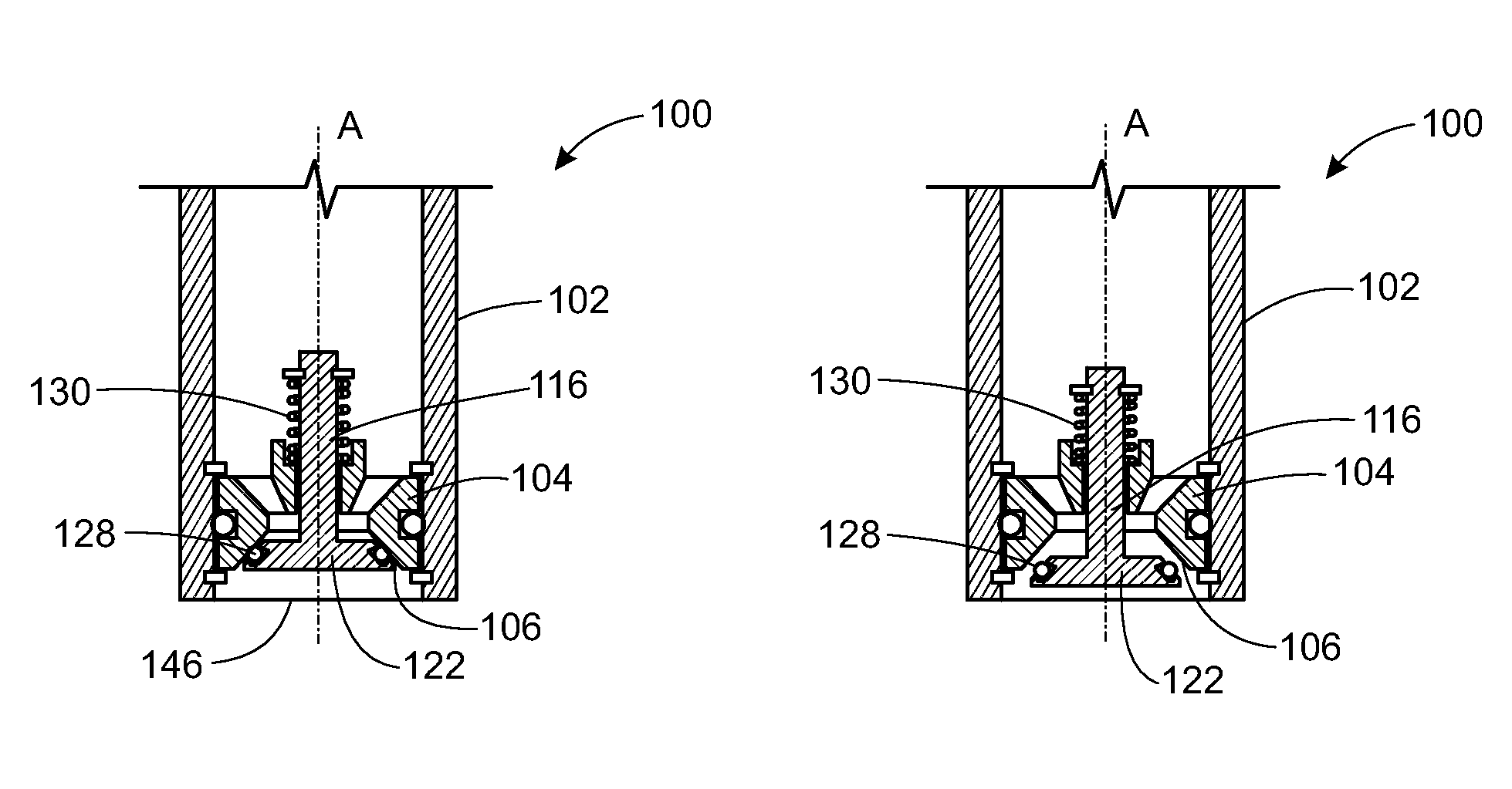
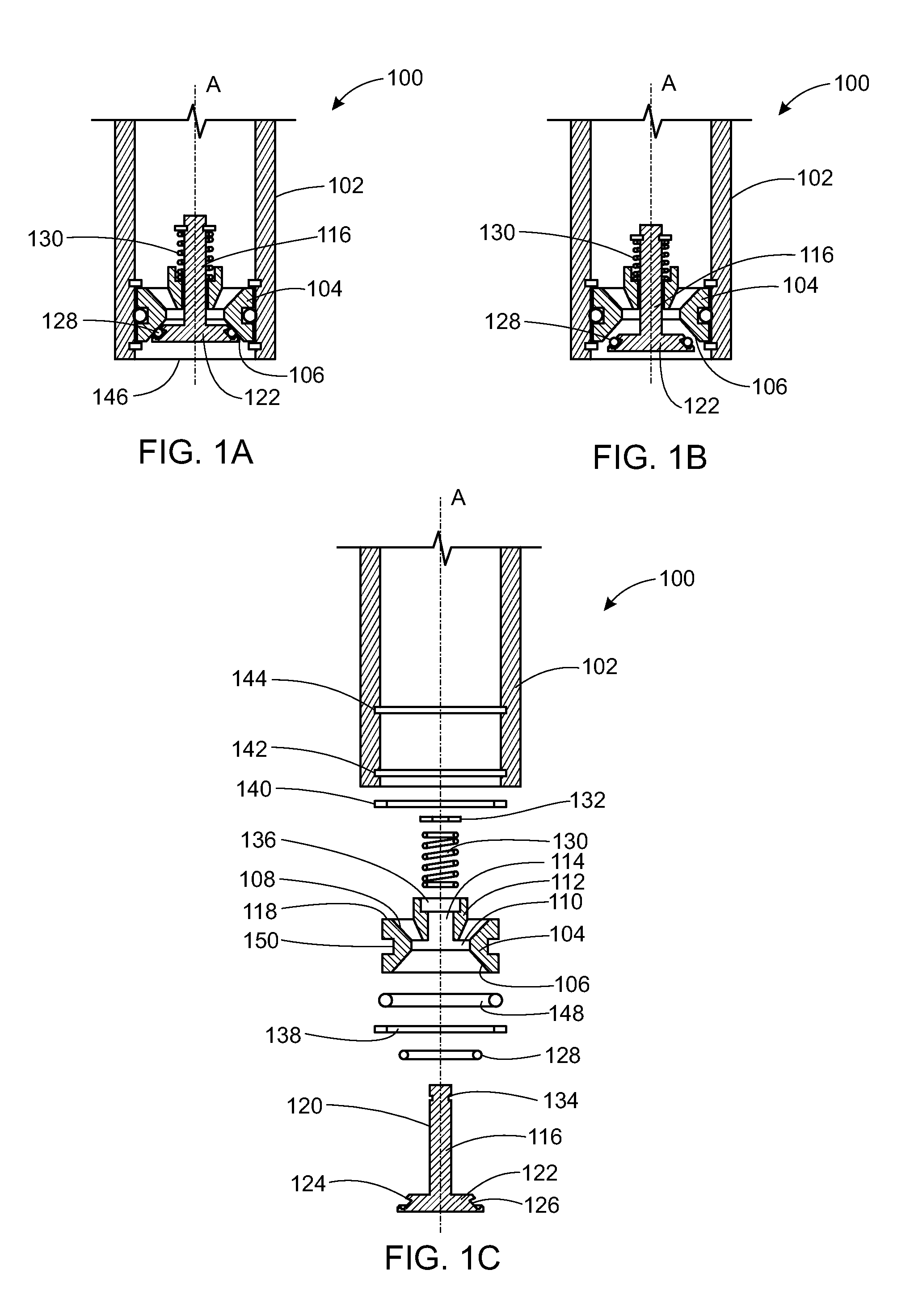
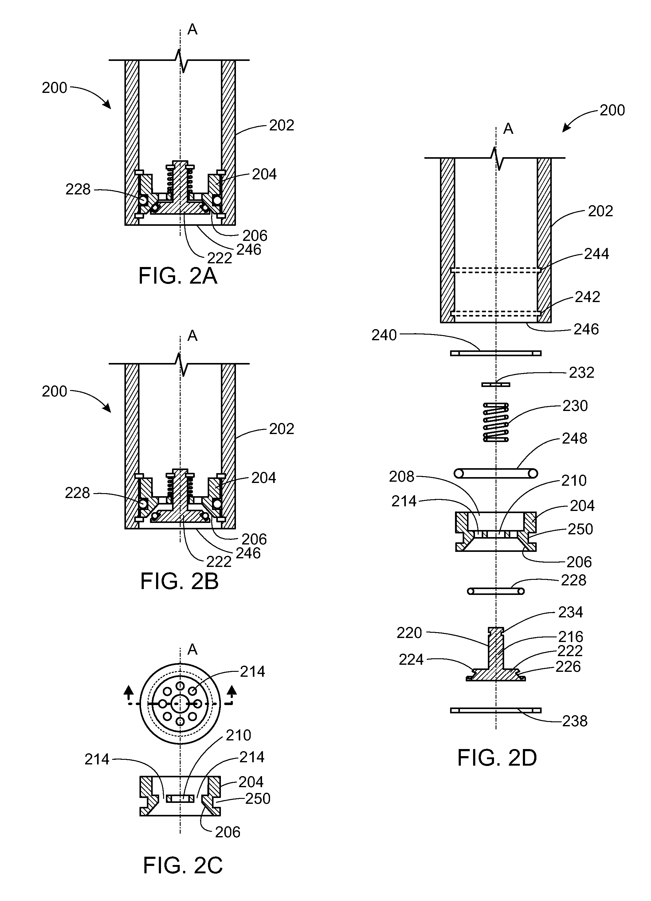
[0017]Referring to FIGS. 1A through 1C, an exemplary embodiment of a dripfree nozzle 100 is shown. The dripfree nozzle 100 is comprised of a gasoline nozzle 102 with a valve assembly affixed inside and near the opening of the nozz...


PUM


Abstract

A device for reducing drips from a nozzle comprising a valve body comprising a frusto-conical outer surface, a first aperture that receives the stem of a movable valve closure mechanism, and one or more additional apertures that allow fluids to flow through the valve body when the valve is opened. In an exemplary embodiment of the invention, the spring biased movable valve closure mechanism comprises a stem extending in the direction of the longitudinal axis of the valve body, a frusto-conical valve head that maintains a fluid barrier seal with the outer surface, and a spring that biases the valve closure mechanism in the direction of the longitudinal axis of the valve body.

Description

BACKGROUND OF THE INVENTION[0001]1. Field of the Invention[0002]The invention relates generally to the field of gasoline nozzles. In particular, the invention relates to a method and system for reducing or eliminating spillage from gasoline nozzles.[0003]2. Description of Related Art[0004]The problem of reducing or eliminating fuel loss related to dripping from gasoline dispenser nozzles has long been recognized, but a cost effective system and method for eliminating drips has proven elusive. Vehicle refueling using existing gasoline nozzle designs results in gasoline vapor and spillage losses through drips from the nozzle, particularly after nozzle shutoff as the device is removed from the fueling port. Gasoline is high in volatile organic compounds (VOCs) and hazardous air pollutants (HAPs), both of which are targeted for reduction / elimination by environmental regulations. It is estimated that such spillage emissions account for 6% or more of vehicle refueling emissions. Thus, a r...

Claims


Application Information

Patent Timeline
IPC IPC(8): F16K1/00
CPCB67D7/42F16K23/00F16K15/063B67D1/1256B67D7/3209
Inventor MILLARD, MATTHEW DAVID
Owner MILLARD MATTHEW DAVID
Learn More