Liquid ejecting apparatus

a technology of liquid ejecting apparatus and ejector, which is applied in the direction of printing mechanism, power drive mechanism, printing, etc., can solve the problems of droplets staining recording paper, etc., and achieve the effect of reducing smearing and coming into conta

Active Publication Date: 2017-08-17
SEIKO EPSON CORP
View PDF4 Cites 7 Cited by
  • Summary
  • Abstract
  • Description
  • Claims
  • Application Information

AI Technical Summary

Benefits of technology

[0016]With this structure, the liquid ejecting head, which configures a line head, has a plurality of nozzles that are arranged such that a recording region extends over the entire medium, and this structure enables the liquid ejecting head to eject the liquid onto the medium that is transported in the transport direction when the medium is stationary. If the medium is moved during a liquid ejecting operation, the medium comes into contact with the liquid ejecting head more easily than when the medium is stationary during the liquid ejecting operation. Accordingly, if waste products such as a liquid adheres to the liquid ejecting head, the medium coming into contact with the liquid ejecting head may result in smearing. In this regard, the liquid ejecting head that is sufficiently wiped by the wiping member can reduce smearing due to the liquid ejecting head coming into contact with the moving medium.

Problems solved by technology

Especially, when the recording head rotates and the lower surface is inclined with respect to the horizontal, the ink accumulated on the side surface at an upper end side of the lower surface may drip down the lower surface toward a lower end, and these droplets may stain recording paper, and the like.
Such a problem is common not only among printers that eject an ink to perform printing, but also among most liquid ejecting apparatuses that have a liquid ejecting section that is arranged facedown, the liquid ejecting section being inclinable with respect to the horizontal.
Accordingly, if waste products such as a liquid adheres to the liquid ejecting head, the medium coming into contact with the liquid ejecting head may result in smearing.

Method used


Image

  • Liquid ejecting apparatus
  • Liquid ejecting apparatus
  • Liquid ejecting apparatus

Examples


Embodiment Construction

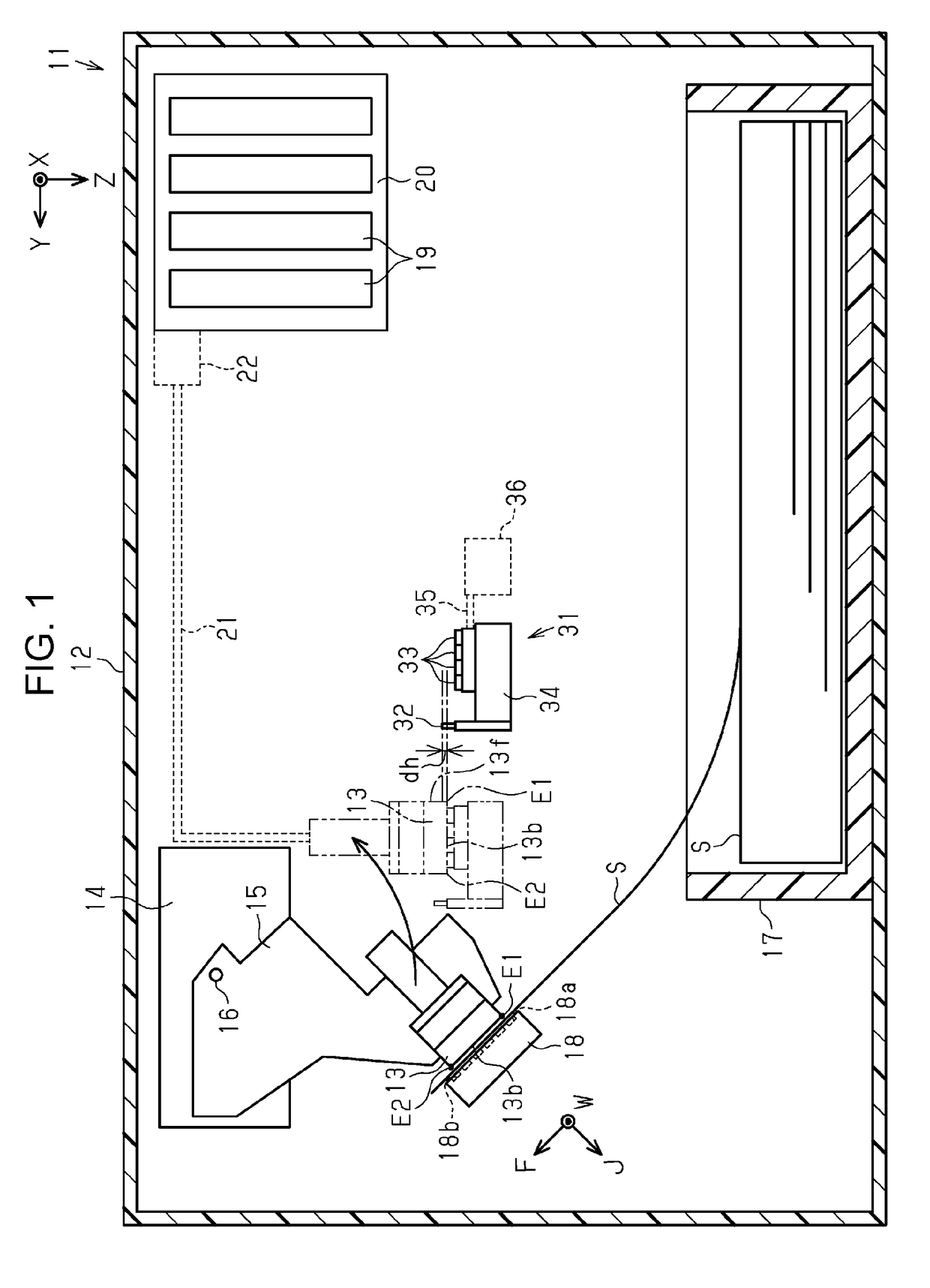
[0025]Hereinafter, a liquid ejecting apparatus according to an embodiment will be described with reference to the attached drawings. The liquid ejecting apparatus is, for example, an ink jet printer that performs recording (printing) by ejecting an ink, which is an example liquid, onto a medium such as paper. In the description below, the direction of gravity Z denotes a vertically downward direction, and the first direction X and the second direction Y denote directions which are orthogonal to each other in horizontal directions.

[0026]As illustrated in FIG. 1, a liquid ejecting apparatus 11 includes a casing 12, a liquid ejecting head 13 that ejects a liquid in the casing 12, a maintenance device 31 that performs maintenance of the liquid ejecting head 13, a displacing mechanism 14 that changes the posture of the liquid ejecting head 13, a cassette 17 that store a plurality of media S, and a supporting base 18 that supports the medium S fed from the cassette 17.

[0027]An attachment ...


PUM


Abstract

A liquid ejecting apparatus includes a liquid ejecting head that has a nozzle opening surface in which the nozzles open, a displacing mechanism formed to change a posture of the liquid ejecting head between a first posture in which the nozzle opening surface is inclined with respect to the horizontal and a second posture in which an inclination of the nozzle opening surface is smaller than the inclination of the nozzle opening surface in the first posture, and a wiping member to wipe the liquid ejecting head. On the nozzle opening surface, if a vertical lower end in the first posture is a first end and a vertical upper end in the first posture is a second end, the wiping member wipes the liquid ejecting head from the first end side toward the second end side when the liquid ejecting head is in the second posture.

Description

BACKGROUND[0001]1. Technical Field[0002]The present invention relates to a liquid ejecting apparatus such as a printer.[0003]2. Related Art[0004]An example of a liquid ejecting apparatus is an ink jet printer that performs a wiping operation for wiping, for example, an ink that has adhered to an ink ejecting section by rubbing the ink ejecting section (a lower surface of a recording head from which the ink is ejected) against a wiping member by rotating the recording head (for example, see JP-A-10-34950).[0005]Waste products such as the ink wiped by the wiping member tend to accumulate on a side surface of the above-mentioned recording head, the side surface intersecting the lower surface with which the wiping member comes into contact. Especially, when the recording head rotates and the lower surface is inclined with respect to the horizontal, the ink accumulated on the side surface at an upper end side of the lower surface may drip down the lower surface toward a lower end, and th...

Claims


Application Information

Patent Timeline
Patent Type & Authority Applications(United States)
IPC IPC(8): B41J2/165
CPCB41J2/16535B41J25/001B41J2/16517B41J2/16538B41J2/16585B41J2/16588B41J25/316
Inventor TAKINO, FUMIYAWATANABE, EIICHIROMORI, KAZUNORI
Owner SEIKO EPSON CORP
Why Eureka
Try Eureka