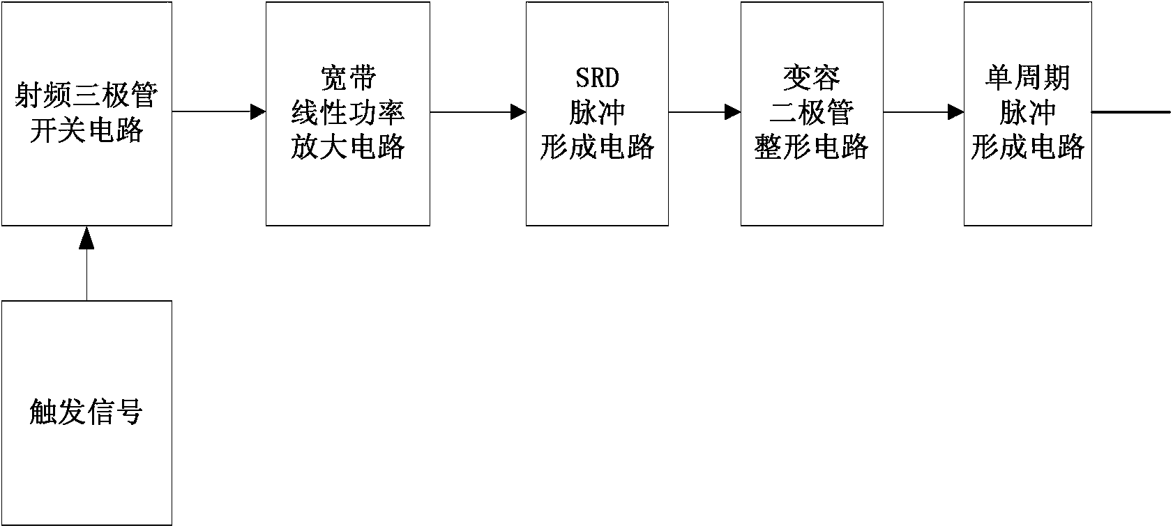
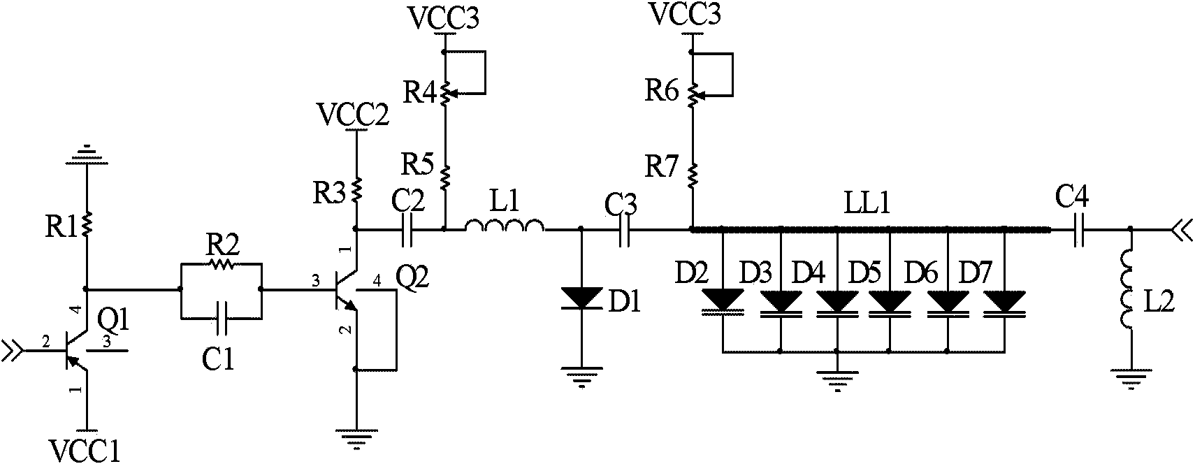
Picosecond single recurrent pulse transmitter

A single-cycle, transmitter technology, applied in the electronic field, can solve the problems of wide pulse bottom, small pulse voltage amplitude, and small output single-cycle pulse amplitude, and achieve the effect of large peak-to-peak amplitude, narrow pulse bottom width, and good symmetry

Active Publication Date: 2014-07-16
INST OF ELECTRONICS CHINESE ACAD OF SCI
View PDF3 Cites 13 Cited by
  • Summary
  • Abstract
  • Description
  • Claims
  • Application Information

AI Technical Summary

Problems solved by technology

However, when these circuits work alone, they all have their own defects: the pulse bottom width generated by the logic circuit is relatively large; the circuit structure designed according to the nonlinear transmission line technology and the laser time domain technology is complex and not easy to debug; the tunnel diode The amplitude of the generated pulse voltage is small; while the avalanche triode requires a high breakdown voltage, a high-voltage power supply module needs to be added
[0005] In the process of realizing the present invention, the applicant found that the above-mentioned single-cycle pulse generation method using a differential circuit to differentiate the unipolar pulse has a large loss of pulse amplitude due to the differential effect, and the output single-cycle pulse amplitude is relatively small. The symmetry and edge rate of the polar pulse signal have high requirements, and the tail of the main pulse generated by the single-cycle pulse is large, and the ringing level is high. When it is connected to the actual dipole transmitting antenna, there is a main Defects such as large tailing at the pulse rear end and serious reflection oscillations affect the shallow detection capability of the high-resolution ultra-wideband radar system

Method used


Image

  • Picosecond single recurrent pulse transmitter
  • Picosecond single recurrent pulse transmitter

Examples


Embodiment Construction

[0014] In order to make the object, technical solution and advantages of the present invention clearer, the present invention will be described in further detail below in conjunction with specific embodiments and with reference to the accompanying drawings. It should be noted that, in the drawings or descriptions of the specification, similar or identical parts all use the same figure numbers. Implementations not shown or described in the accompanying drawings are forms known to those of ordinary skill in the art. Additionally, while illustrations of parameters including particular values ​​may be provided herein, it should be understood that the parameters need not be exactly equal to the corresponding values, but rather may approximate the corresponding values ​​within acceptable error margins or design constraints. The directional terms mentioned in the embodiments, such as "upper", "lower", "front", "rear", "left", "right", etc., are only referring to the directions of the...


PUM


Abstract

The invention provides a picosecond single recurrent pulse transmitter. Picosecond single recurrent pulse signals are generated according to the switching characteristics of a radio frequency audion, the driving capacity of a broadband linear power amplifying audion, the phase step characteristics of a phase step recovery diode, the capacitance variable characteristics of a variable capacitance diode, the total reflection characteristics of a micro-strip short-circuit wire and the like, the output pulse positive and negative polarity symmetry is good, the peak-to-peak value amplitude is large, the pulse bottom width and trailing are small, and the picosecond single recurrent pulse transmitter is suitable for the high-resolution pulse type ultra wide band radar system application.

Description

technical field [0001] The invention relates to the field of electronic technology, in particular to a picosecond-level single-period pulse transmitter. Background technique [0002] UWB technology has many attractive features, such as low power, strong penetration capability, high positioning accuracy, high data transmission rate, etc. Therefore, UWB technology is widely used in daily life. For example, ultra-wideband technology can be applied to ground-penetrating radar, through-wall radar, life detection radar, radar imaging, precise positioning and tracking and other fields. Under the authorization of the Federal Communications Commission (FCC), the UWB technology is applied to communication systems to meet the requirements of short distance and high data rate. [0003] The pulse generator is an important part of the ultra-wideband system. To a certain extent, the output pulse bandwidth of the pulse transmitter determines the working bandwidth of the ultra-wideband syst...

Claims


Application Information

Patent Timeline
Patent Type & Authority Applications(China)
IPC IPC(8): H03K5/02
Inventor 刘丽华夏新凡管洪飞张群英方广有
Owner INST OF ELECTRONICS CHINESE ACAD OF SCI
Why Eureka
Try Eureka