Inspection apparatus and inspection method of magnetic sensor

a technology of magnetic sensor and inspection apparatus, which is applied in the direction of magnetic measurement, single device manufacturing, instruments, etc., can solve the problems of degrading the accuracy of inspection of the foregoing technologies of plt 1 and plt 2, and the loss of financial assembling cost, so as to improve the inspection accuracy, easy to inspect variations of magnetic properties, and accurately generate the desired magnetic field

Inactive Publication Date: 2013-02-14
YAMAHA CORP
View PDF17 Cites 36 Cited by
  • Summary
  • Abstract
  • Description
  • Claims
  • Application Information

AI Technical Summary

Benefits of technology

[0019]Moreover, it is possible to install a temperature adjuster which is able to adjust the stage temperature at a desired temperature. This makes it possible to easily inspect variations of magnetic property at different temperatures. In this connection, it is possible to feed back the stage temperature to the magnetic field controller in addition to the measurement result of the temperature environment measuring sensors.
[0020]As described above, the present invention is designed to concurrently inspect a wafer-like array of magnetic sensors instead of individual pieces of magnetic sensors which are separated from each other, wherein a magnetic field is applied to the magnetic sensors collectively so as to concurrently inspect magnetic properties of magnetic sensors. Additionally, a magnetic field currently exerted in the measurement area is measured with the magnetic field environment measuring sensors, installed in the probe card, and fed back to the magnetic field controller, which in turn controls the magnetic field generating coils to accurately generate a desired magnetic field with desired intensity and desired directivity. Thus, it is possible to improve inspection accuracy when inspecting magnetic properties of magnetic sensors.

Problems solved by technology

Inspecting each single magnetic sensor enclosed in its package needs troublesomeness treatment and may suffer a financial loss in the assembling cost of magnetic sensors which are determined as defective ones through inspection.
The foregoing technologies disclosed in PLT 1 and PLT 2 utilize a probe card equipped with a coil; hence, it is difficult to enlarge the size of a coil due to its structural limitation.
That is, the foregoing technologies of PLT 1 and PLT 2 may be degraded in their accuracy of inspection results because they simply control an electric current to determine whether or not a desired magnetic field is generated with a coil
This arrangement may not accurately detect a magnetic field affecting a magnetic sensor installed in the socket.
That is, this technology may suffer from low inspection accuracy.

Method used


Image

  • Inspection apparatus and inspection method of magnetic sensor
  • Inspection apparatus and inspection method of magnetic sensor
  • Inspection apparatus and inspection method of magnetic sensor

Examples


Embodiment Construction

[0028]The present invention will be described in further detail by way of examples with reference to the accompanying drawings.

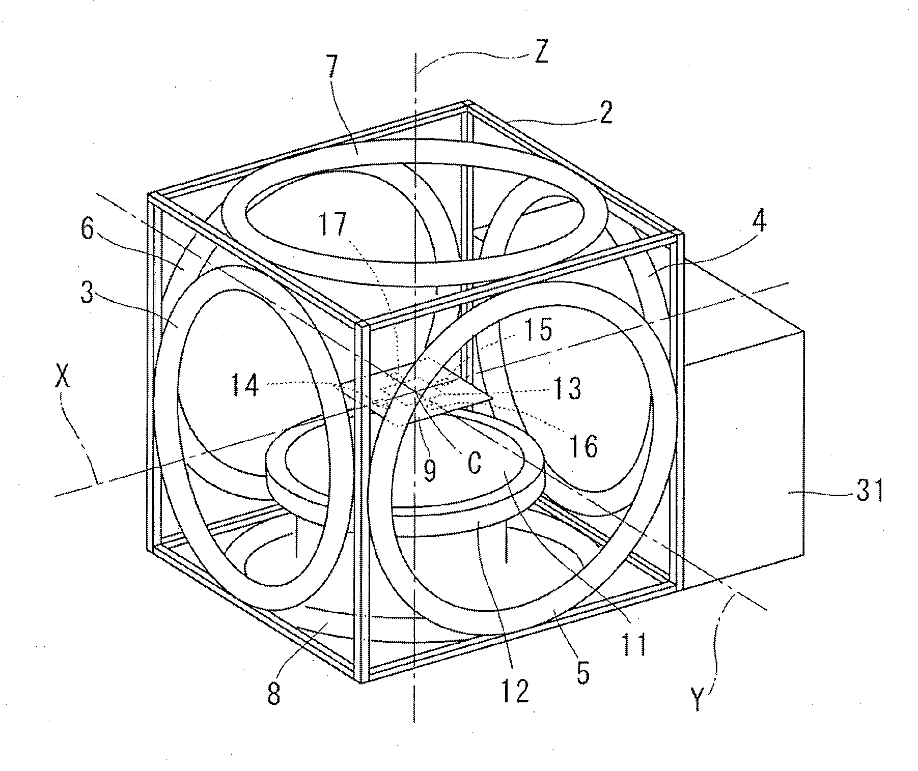
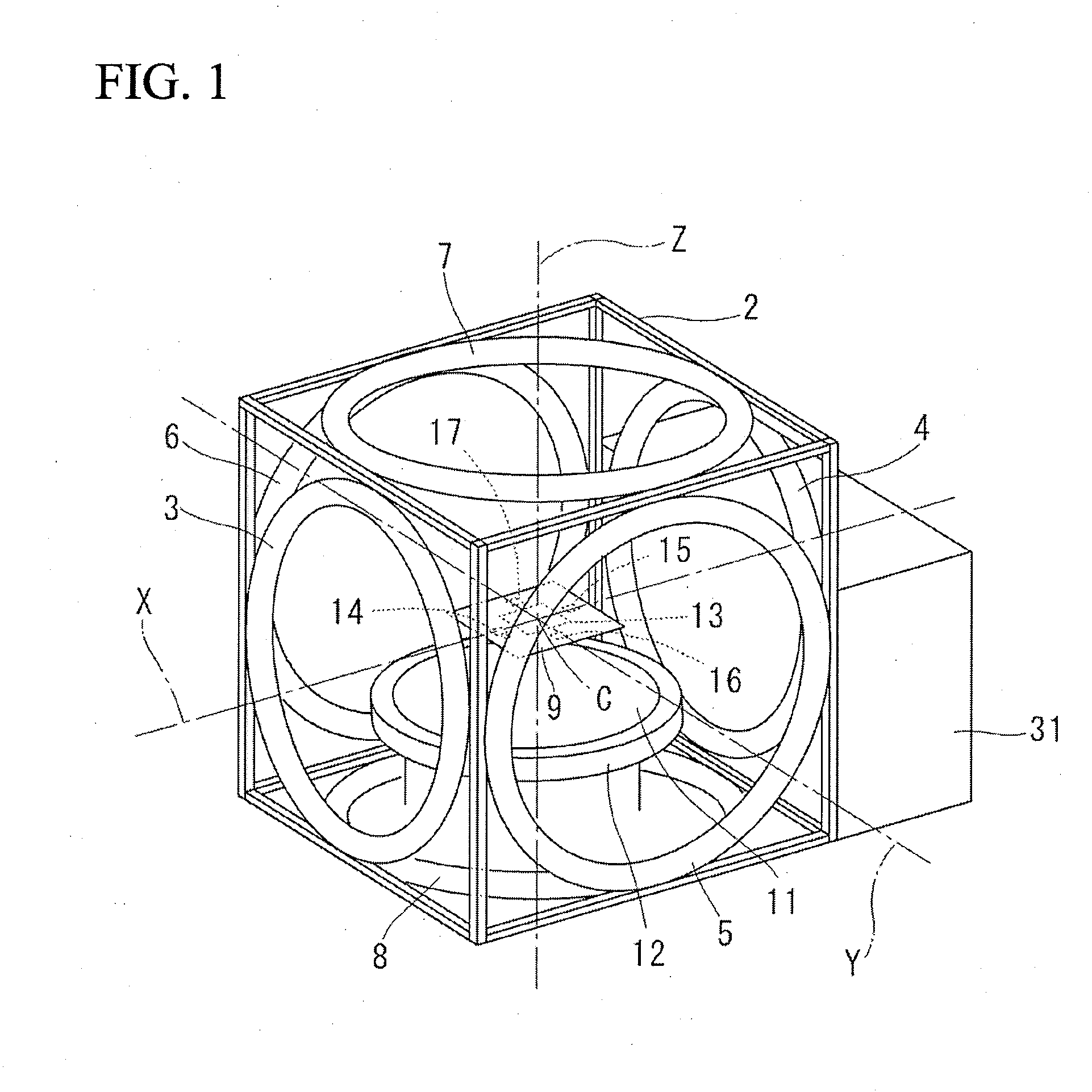
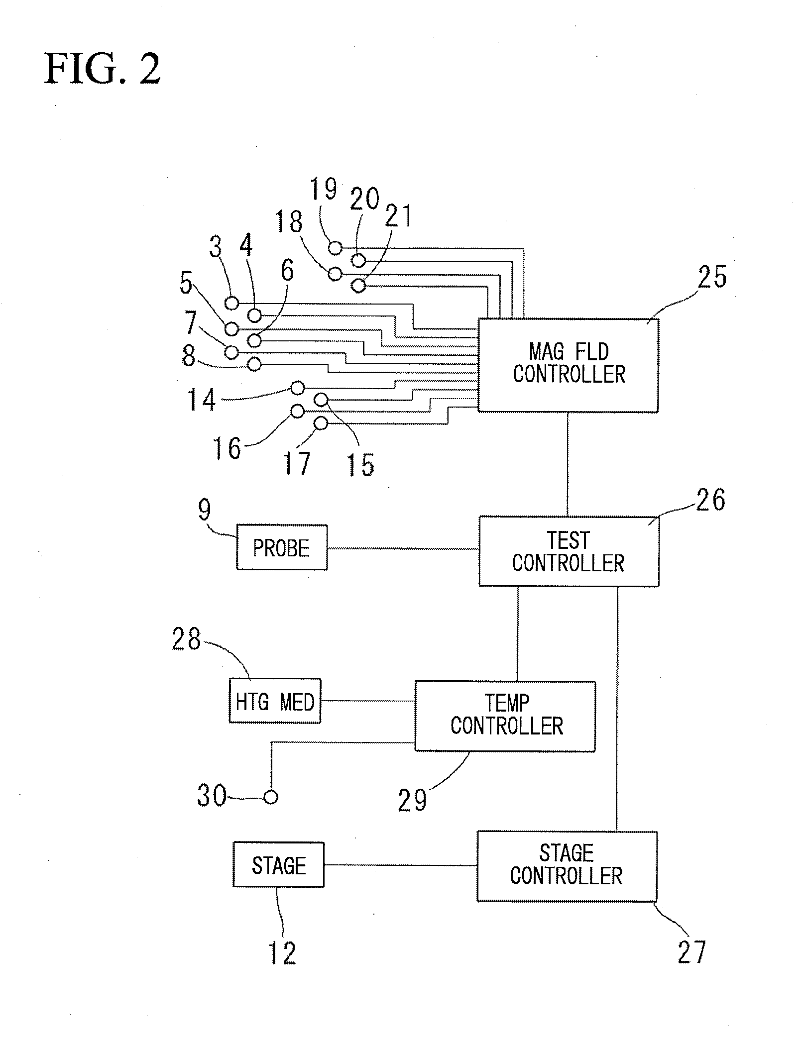
[0029]FIG. 1 is a perspective view of a magnetic sensor inspection apparatus 1 according to a preferred embodiment of the present invention. The entire structure of the magnetic sensor inspection apparatus 1 is defined using a frame 2 equipped with which six magnetic field generating coils 3 to 8 and a single probe card 9. The frame 2 is equipped with a movable stage 12 for mounting a sensor aggregation 11 which is a wafer-like array of magnetic sensors 10.

[0030]The magnetic field generating coils 3 to 8 are subdivided into plural pairs of coils, in which two coils are paired and arranged opposite to each other in an axial direction. The magnetic field generating coils 3, 4 are paired and attached to the left and right sides of the frame 2; the magnetic field generating coils 5, 6 are paired and attached to the front and rear sides of the frame 2; the magnet...


PUM


Abstract

A magnetic sensor inspection apparatus has a rectangular frame including a stage, a probe card, and a plurality of magnetic field generating coils. A wafer-like array of magnetic sensors is mounted on the stage, which is movable in horizontal and vertical directions. The probe card includes a plurality of probes which are brought into contact with a plurality of magnetic sensors encompassed in a measurement area. The magnetic field generating coils are driven to generate a magnetic field toward the stage. A plurality of magnetic field environment measuring sensors is arranged in the peripheral portion of the probe card surrounding the probes. A magnetic field controller controls magnetic fields generated by the magnetic field generating coils based on the measurement result of the magnetic field environment measuring sensors. Thus, it is possible to concurrently inspect a wafer-like array of magnetic sensors with the probe card.

Description

BACKGROUND OF THE INVENTION[0001]1. Field of the Invention[0002]The present invention relates to an inspection apparatus and an inspection method for use in inspection routines of magnetic sensors, in particularly for use in routines of inspecting a wafer-like array of magnetic sensors in terms of their magnetic property and sensitivity via magnetic property testing under predetermined environmental conditions.[0003]The present application claims priority on Japanese Patent Application No. 2011-175337, the content of which is incorporated herein by reference.[0004]2. Description of the Related Art[0005]According to conventionally-known inspection routines of magnetic properties of magnetic sensors, magnetic sensors are each placed in a magnetic field which is generated using magnetic field generating coils such as Helmholtz coils and subsequently subjected to testing to measure their output signals. Inspecting each single magnetic sensor enclosed in its package needs troublesomeness...

Claims


Application Information

Patent Timeline
Patent Type & Authority Applications(United States)
IPC IPC(8): G01R35/00
CPCG01R35/00G01R33/0052G01R33/0035
Inventor SUZUKI, TAKASHI
Owner YAMAHA CORP
Why Eureka
Try Eureka