
Ink supply apparatus

Inactive Publication Date: 2013-02-21
KOMORI CORP
View PDF11 Cites 0 Cited by
  • Summary
  • Abstract
  • Description
  • Claims
  • Application Information

AI Technical Summary

Benefits of technology

The present invention provides an ink supply apparatus that reduces the load of cleaning by reducing the amount of ink dropping during printing. This is achieved through the use of an ink guide portion that increases the ink transfer time from the ink fountain to the ink fountain roller and reduces the amount of untransferred ink. This, in turn, decreases the cleaning operation load and increases the cleaning interval, improving the printing press's capacity utilization. Additionally, the ink collected from the guide portion is partially collected by a roller, further reducing the load on the cleaning operation of the ink pan and improving printing quality.

Problems solved by technology

Additionally, since the ink that drops from the ink guide portion is partially collected by a roller, the amount of ink collected by the ink pan further decreases.

Method used


Image

  • Ink supply apparatus
  • Ink supply apparatus
  • Ink supply apparatus

Examples


first embodiment

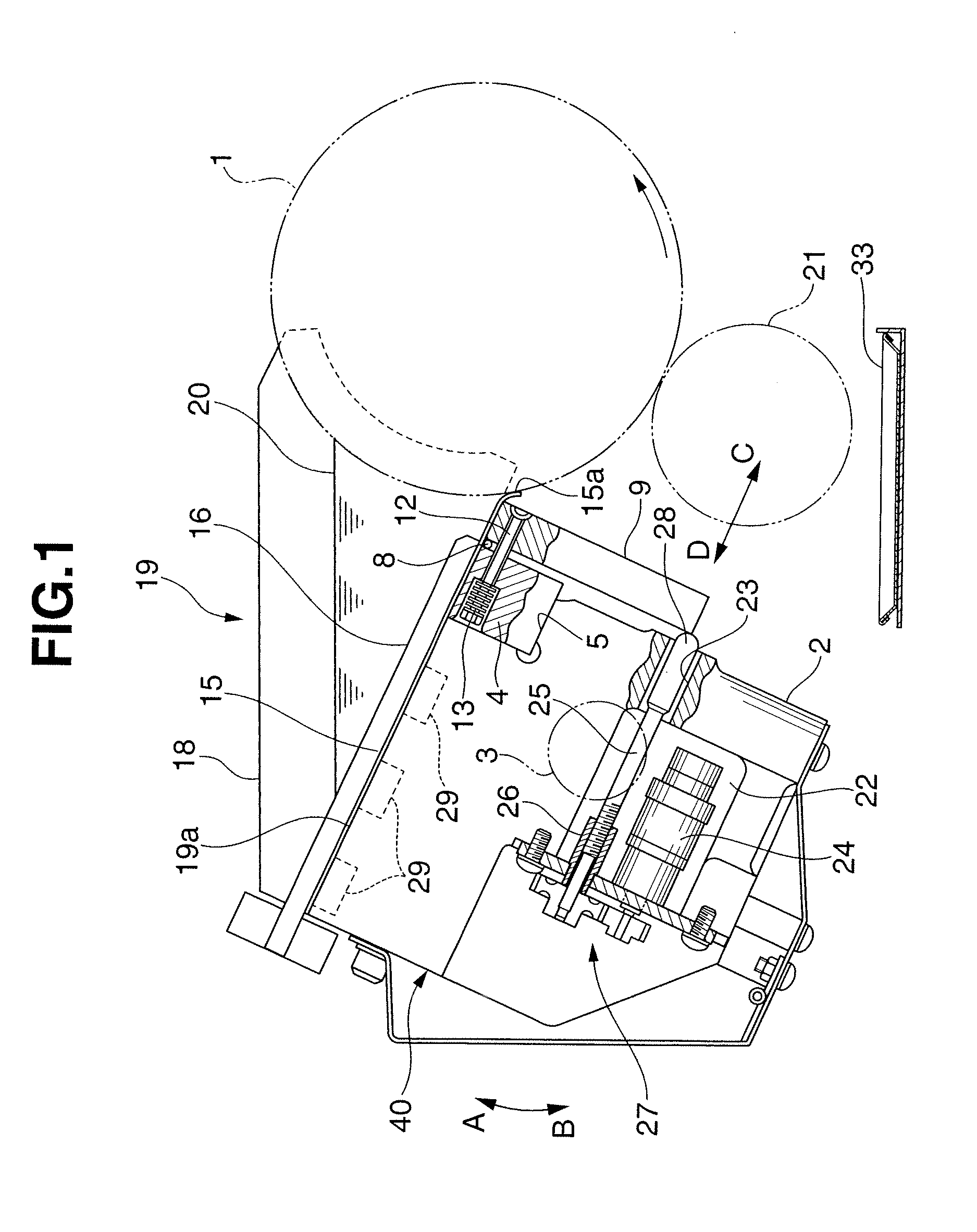
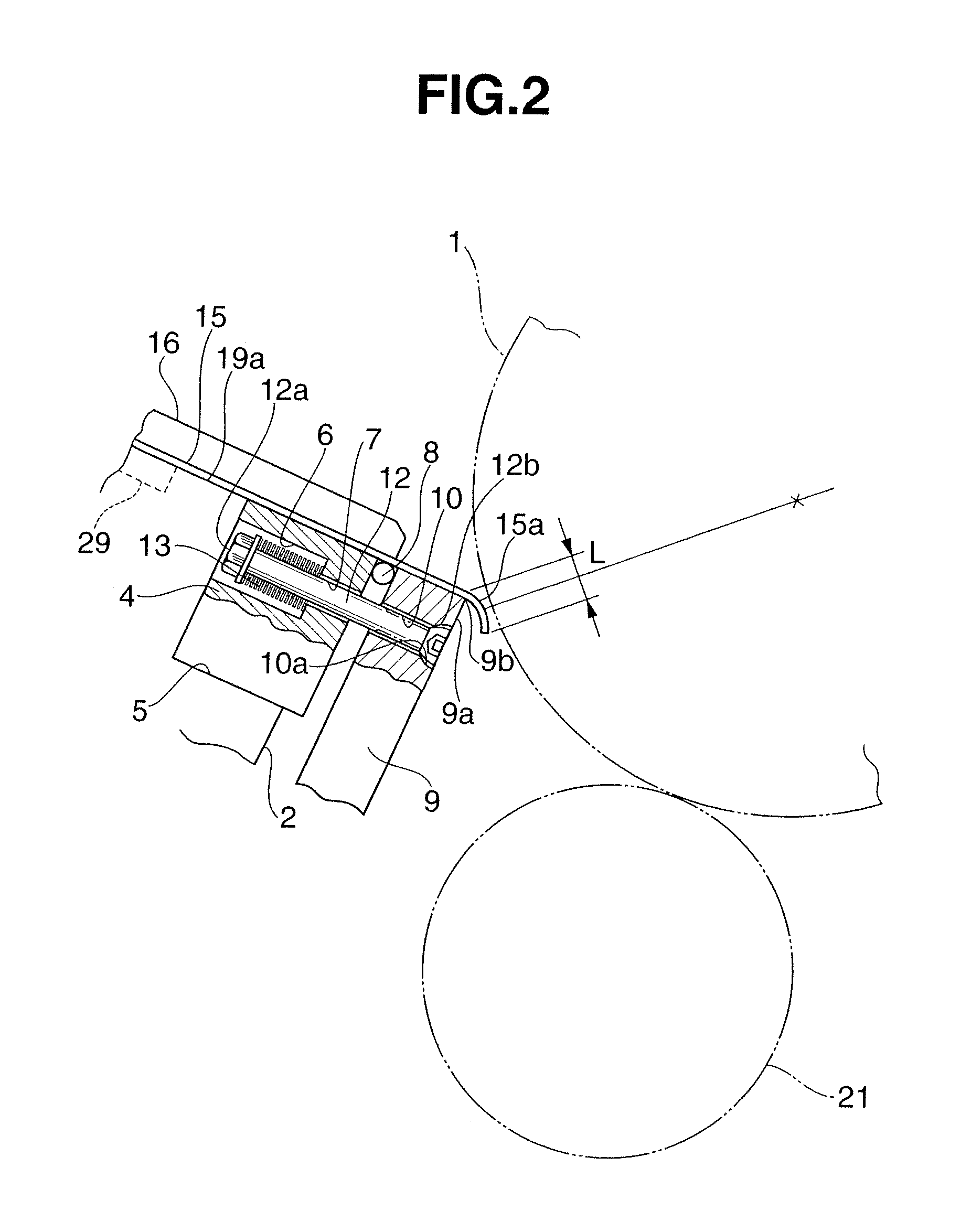
[0014]The first embodiment of the present invention will be described first with reference to FIGS. 1 and 2. An ink fountain roller 1 according to this embodiment is rotatably supported between a pair of machine base frames (not shown) and rotates in a direction from ink fountain keys 9 to an oscillating roller 21 to be described later (counterclockwise in FIG. 1) during an operation. As shown in FIG. 1, an ink fountain key support base 2 that is the ink fountain main body is provided on the rear side of the ink fountain roller 1 and runs slightly longer than the cylinder of the ink fountain roller 1. A support pin 3 is embedded in the machine base frames. The ink fountain key support base 2 is supported to pivot in directions to move close to and separate from the ink fountain roller 1, that is, clockwise and counterclockwise (the directions of arrows A and B) in FIG. 2 about the support pin 3 serving as the pivotal center.

[0015]A holding bar 4 is attached to a groove 5 formed in t...

second embodiment

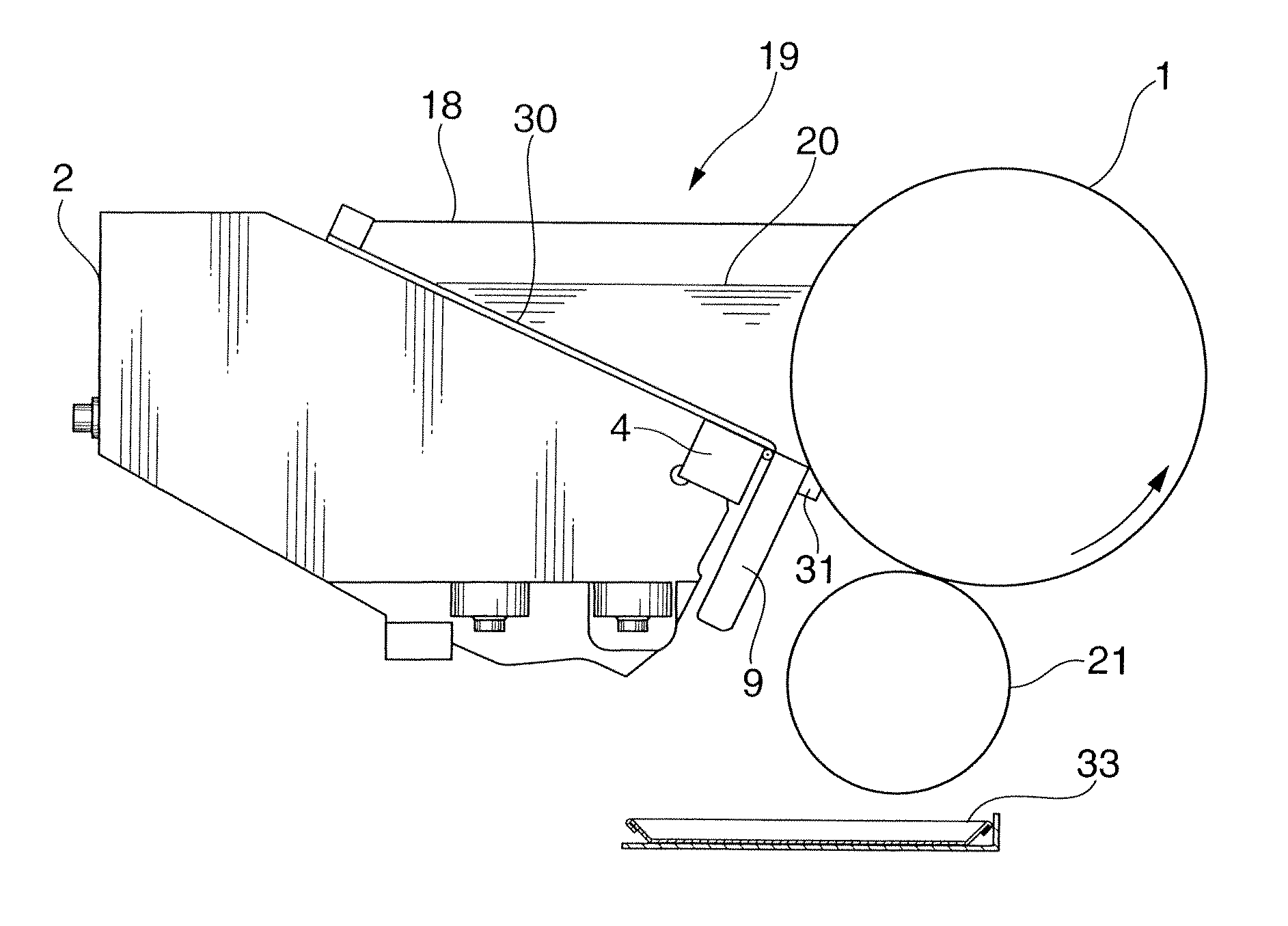
[0029]The second embodiment of the present invention will be described next with reference to FIGS. 3 and 4. In the second embodiment, not the sheet 15 but a bottom plate 30 formed from a thin steel plate is magnetically attracted by magnets (not shown) buried in an ink fountain key support base 2 and a holding bar 4, unlike the first embodiment. In this embodiment, ink 20 is stored in an ink fountain 19 surrounded by the bottom plate 30, ink fountain keys 9, a pair of ink dams 18, and the outer peripheral surface of an ink fountain roller 1.

[0030]In the second embodiment, an ink guide member 31 having an almost rectangular parallelepiped shape and the same length as the width of the ink fountain key 9 is integrally fixed to an end face 9a of each ink fountain key 9, as shown in FIG. 4. The upper surface of the ink guide member 31 is provided with a circular ink guide portion 31a having one end starting from an angled portion 9b and facing the outer peripheral surface of the ink fou...


PUM


Abstract

An ink supply apparatus includes an ink fountain, ink fountain keys, and an ink guide portion. The ink fountain is formed from a pair of ink dams arranged to face each other, a bottom surface, and an outer peripheral surface of an ink fountain roller so as to store ink. The ink fountain keys that form gaps between the outer peripheral surface of the ink fountain roller and the ink fountain keys to extract the ink stored in the ink fountain. The ink guide portion projects from a distal end of each of the ink fountain keys toward the ink fountain roller so as to guide the ink extracted from the ink fountain to the ink fountain roller.

Description

BACKGROUND OF THE INVENTION[0001]The present invention relates to an ink supply apparatus for supplying ink to a printing press.[0002]As described in Japanese Patent Laid-Open No. 2007-237537, a conventional ink supply apparatus includes an ink fountain which is surrounded by a bottom plate fixed on the upper surface of a fountain key support base, a pair of ink dams standing on the two ends of the fountain key support base in the widthwise direction, a plurality of ink fountain keys juxtaposed in the axis direction of an ink fountain roller to be close to its outer peripheral surface, and the outer peripheral surface of the ink fountain roller. Ink in the ink fountain is extracted from a gap formed between the ink fountain keys and the ink fountain roller to the ink fountain roller side. The extracted ink is evened by an oscillating roller facing (contacting) the ink fountain roller and then supplied to the printing press side.[0003]In the above-described conventional ink supply ap...

Claims


Application Information

Patent Timeline
IPC IPC(8): B41F31/02
CPCB41P2231/12B41F31/04
Inventor KAMODA, HIROYOSHIKOMURO, ISAOKUSAKA, AKEHIRO
Owner KOMORI CORP
Learn More