Distributed logical l3 routing

a technology of distributed logical and routing, applied in the direction of digital transmission, data switching network, electrical apparatus, etc., can solve the problems of increasing processing difficulty, l2 domains cannot scale to large sizes, and hamper at least one other

Active Publication Date: 2013-02-21
NICIRA
View PDF29 Cites 645 Cited by
  • Summary
  • Abstract
  • Description
  • Claims
  • Application Information

AI Technical Summary

Benefits of technology

[0005]Some embodiments in some cases model logical routing as an act of interconnecting two or more logical datapath (LDP) sets operating in L2 domains by a logical router that implements a logical datapath set (LDPS) operating in an L3 domain. A packet traversing from a logical L2 domain to another will take the following four steps in some

Problems solved by technology

This process is of increased difficulty where the network switching elements are shared across multiple users.
Many approaches taken to address one of these goals results in hampering at least one of the other

Method used


Image

  • Distributed logical l3 routing
  • Distributed logical l3 routing
  • Distributed logical l3 routing

Examples


Embodiment Construction

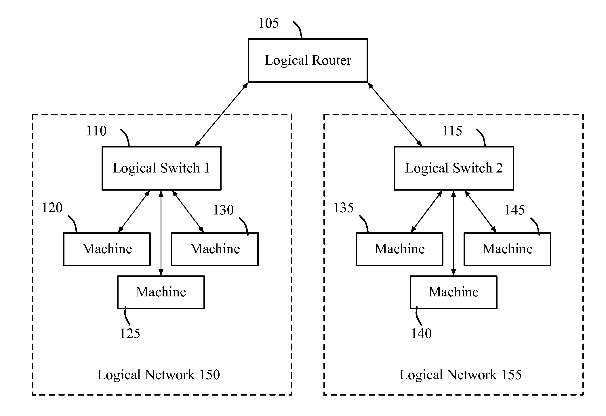
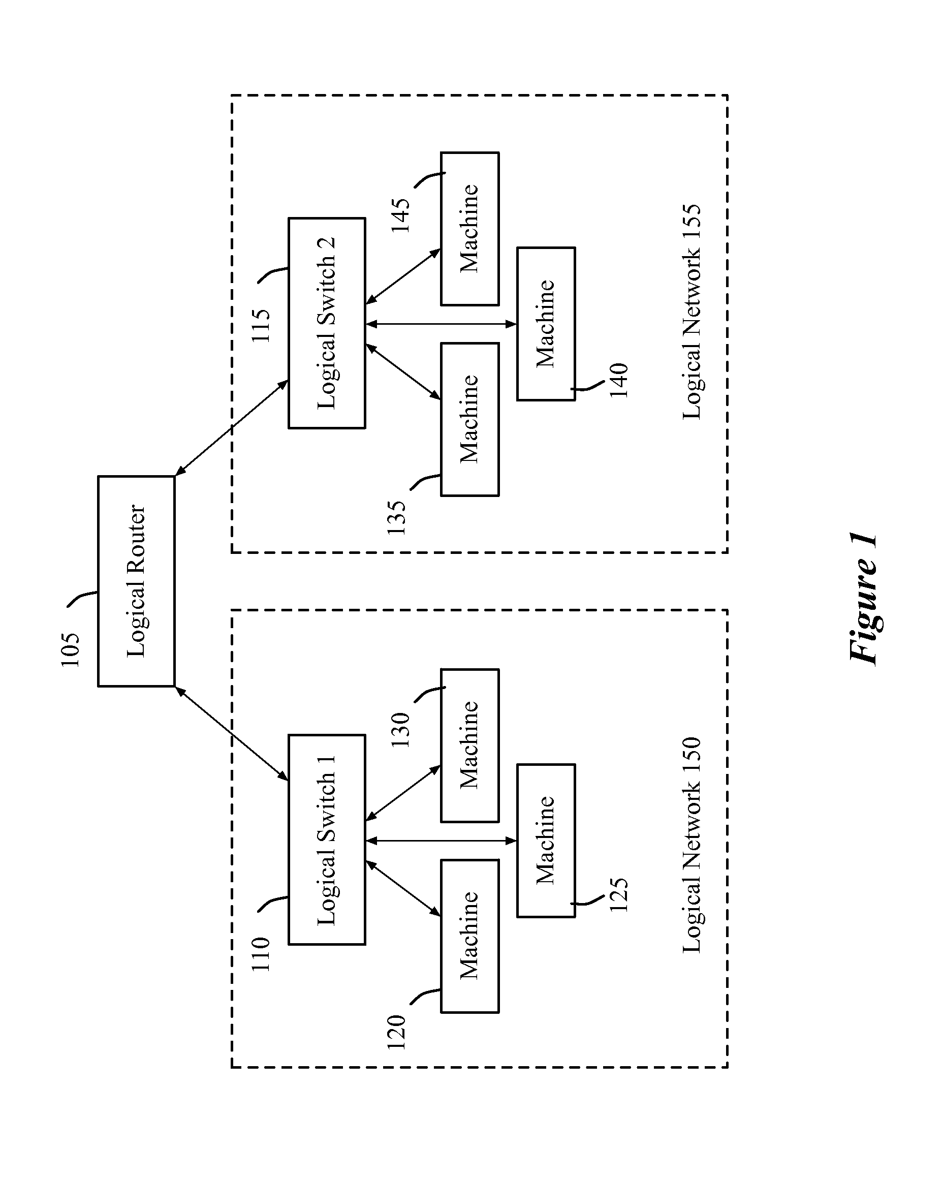
[0082]Some embodiments of the invention provide a network control system that allows logical datapath (LDP) sets (e.g., logical networks) to be implemented by switching elements of a physical network. To implement LDP sets, the network control system of some embodiments generates physical control plane data from logical forwarding plane data. The physical control plane data is then pushed to the managed switching elements, where it is typically converted into physical forwarding plane data that allows the managed switching elements to perform their forwarding decisions. Based on the physical forwarding data, the managed switching elements can process data packets in accordance with the logical processing rules specified within the physical control plane data.

[0083]A single logical datapath set provides switching fabric to interconnect a number of logical ports, which can be either attached to physical or virtual endpoints. In some embodiments, the creation and use of such LDP sets a...


PUM


Abstract

A novel method for configuring first and second managed forwarding elements to perform logical L2 switching and L3 routing is described. The method generates a first set of flow entries for configuring the first managed forwarding element to perform logical L2 ingress processing and L3 routing processing. The method generates a second set of flow entries for configuring the second managed forwarding element to performing logical L2 egress processing.

Description

CLAIM OF BENEFIT TO PRIOR APPLICATIONS[0001]This application claims priority to U.S. Provisional Patent Application 61 / 524,754, filed Aug. 17, 2011, to U.S. Provisional Patent Application 61 / 643,339, filed May 6, 2012, to U.S. Provisional Patent Application 61 / 654,121, filed Jun. 1, 2012, and to U.S. Provisional Patent Application 61 / 666,876, filed Jul. 1, 2012. U.S. Provisional Patent Applications 61 / 524,754, 61 / 643,339, 61 / 654,121, and 61 / 666,876 are incorporated herein by reference.BACKGROUND[0002]Many current enterprises have large and sophisticated networks comprising switches, hubs, routers, servers, workstations and other networked devices, which support a variety of connections, applications and systems. The increased sophistication of computer networking, including virtual machine migration, dynamic workloads, multi-tenancy, and customer specific quality of service and security configurations require a better paradigm for network control. Networks have traditionally been ma...

Claims


Application Information

Patent Timeline
IPC IPC(8): H04L12/28H04L45/74
CPCH04L47/12H04L47/125H04L41/0803H04L45/54H04L61/103H04L45/74H04L61/256H04L45/04H04L61/2592
Inventor KOPONEN, TEEMUZHANG, RONGHUACASADO, MARTINTHAKKAR, PANKAJGROSS, IV, JESSE E.WENDLANDT, DANIEL J.MAHAJAN, MEHAK
Owner NICIRA
Why Eureka
Try Eureka