Method and apparatus for control channel transmission and reception

a control channel and transmission channel technology, applied in the field of wireless communication systems, can solve the problems of resource wastage, 3gpp standards do not address the search of control channels,

Inactive Publication Date: 2013-02-21
GOOGLE TECH HLDG LLC
View PDF9 Cites 216 Cited by
  • Summary
  • Abstract
  • Description
  • Claims
  • Application Information

AI Technical Summary

Benefits of technology

[0005]In order to decode the information sent on PDCCH, the UE needs to perform channel estimation for coherent demodulation of the PDCCH. To perform channel estimation, the UE receives Reference Signals (RSs), for example, pilot symbols, that are Cell-specific reference signals (CRS) and included in the subframe and that are associated with one or more antenna ports. For example, in 3GPP LTE Releases 8, 9, and 10, the UE uses the CRSs associated with one or more of antenna ports 0, 1, 2, and 3 for receiving the PDCCH. The number of antenna ports used for demodulating control channels is determined from decoding of the Physical Broadcast Channel (PBCH) that is transmitted in known Resource blocks in subframe 0. Typically, transmit diversity scheme is used when more than one antenna port is used for control channel demodulation. An antenna port is defined such that a channel over which a symbol on the antenna port is conveyed can be inferred from the channel over which another symbol on the same antenna port is conveyed. The Reference Signals (RS) structure for antenna ports 0, 1, 2, and 3 is shown in FIG. 1, wherein RSs labeled R0 are resource elements carrying RSs associated with antenna port 0, RSs labeled R1 are resource elements carrying RSs associated with antenna port 1, RSs labeled R2 are resource elements carrying RSs associated with antenna port 2, and RSs labeled R3 are resource elements carrying RSs associated with antenna port 3.

Problems solved by technology

The 3GPP standards do not address how a control channel search space and a blind decoding for a user is configured with respect to antenna ports, etc.
On the other hand, if all users in a cell are configured with different sets of RBs different antenna ports for DL control signaling, then there is resource wastage.

Method used


Image

  • Method and apparatus for control channel transmission and reception
  • Method and apparatus for control channel transmission and reception
  • Method and apparatus for control channel transmission and reception

Examples


Embodiment Construction

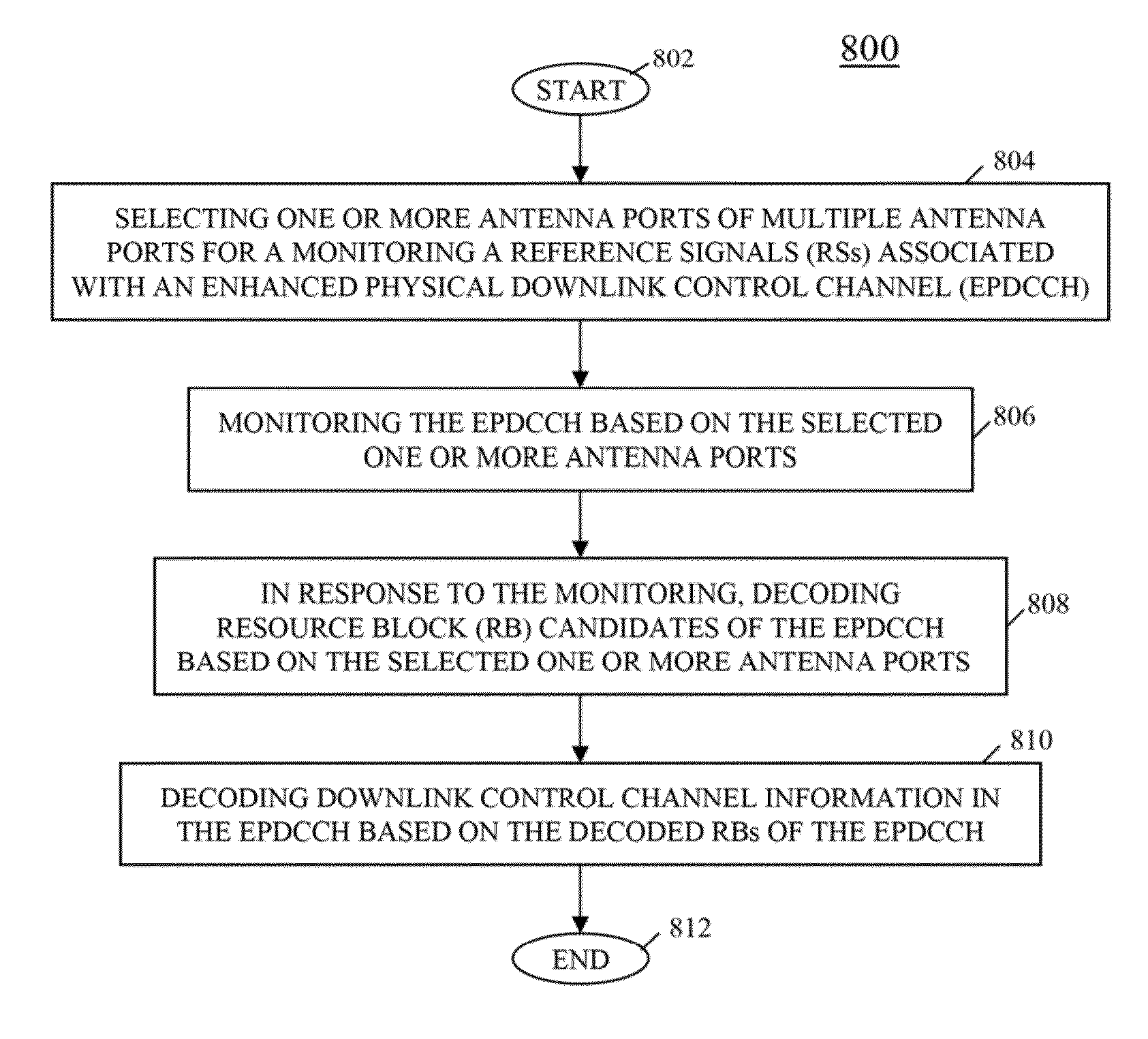
[0024]In order to address the need for defining a control channel search space and / or a blind decoding configuration that can improve resource efficiency, multiplexing efficiency, and reduced and randomized control channel blocking, while also allowing a reasonable blind decoding complexity at a user equipment (UE), a communication system is provided wherein the UE receives control information from a wireless network and decodes the received control information. More particularly, the UE receives a subframe comprising a plurality of time-frequency resources, the time-frequency resources comprising at least two control channel candidates. The UE determines a first control channel candidate of the at least two control channel candidates in the subframe, determines at least one first antenna port associated with the first control channel candidate, decodes the first control channel candidate based on the determined at least one first antenna port, determines a second control channel ca...


PUM


Abstract

A user equipment (UE) receives a signal comprising multiple resource blocks and configured for receiving a subframe comprising multiple time-frequency resources, the time-frequency resources comprising at least two control channel candidates. The UE determines a first control channel candidate of the at least two control channel candidates in the subframe, determines a first antenna port (AP) associated with the first control channel candidate, decodes the first control channel candidate based on the first AP, determines a second control channel candidate of the at least two control channel candidates in the subframe, determines a second AP associated with the second control channel candidate, and decodes the second control channel candidate based on the second AP, wherein the AP used for decoding the first control channel candidate is distinct from the AP used for decoding the second control channel candidate.

Description

RELATED APPLICATIONS[0001]This application claims priority to U.S. Patent Application No. 61 / 523,586 filed Aug. 15, 2011.CROSS-REFERENCE TO RELATED APPLICATIONS[0002]This application is related to U.S. patent application Ser. No. ______, attorney docket no. CS39046, entitled “METHOD AND APPARATUS FOR CONTROL CHANNEL TRANSMISSION AND RECEPTION,” and filed on the same date as this application.FIELD OF THE INVENTION[0003]The present disclosure relates generally to wireless communication systems, and more particularly to control channel transmission and reception in an Orthogonal Frequency Division Multiplexing (OFDM) communication system.BACKGROUND OF THE INVENTION[0004]In current 3GPP LTE (Third Generation Partnership Project Long Term Evolution) communication systems, that is, Releases 8, 9, and 10, downlink (DL) control signaling from an eNodeB is received by a user equipment (UE) in the first three (or four) symbols of a subframe (typically less than 3 for large system bandwidths s...

Claims


Application Information

Patent Timeline
Patent Type & Authority Applications(United States)
IPC IPC(8): H04W72/04
CPCH04L5/0023H04L5/0092H04L5/0053H04L5/0051
Inventor NORY, RAVIKIRANKRISHNAMURTHY, SANDEEP H.LOVE, ROBERT T.NANGIA, VIJAYNIMBALKER, AJITSAYANA, KRISHNA KAMALZHUANG, XIANGYANG
Owner GOOGLE TECH HLDG LLC
Why Eureka
Try Eureka