Lifting device for a rotor of a wind turbine

Inactive Publication Date: 2013-02-21
SUZLON ENERGY GMBH (DE)
View PDF8 Cites 12 Cited by
  • Summary
  • Abstract
  • Description
  • Claims
  • Application Information

AI Technical Summary

Benefits of technology

[0012]For the inventive solution, it may be also advantageous if each of the half shells of the receiving device owns an underside facing the blade root and if an elastic layer, which may also be applied directly onto the underside of the half-shells, protects the surface of the rotor in load situations. Wear by abrasion and friction can be prevented or a

Problems solved by technology

However, problems often occur in this type of pulleys, which make a lifting of the rotor and a assembling onto the turbine housing evidently more difficult, particularly for larger wind turbine facilities.
This is particularly disadvantageous, since through this adhesion and friction forces the center of gravity of the crane suspension is abruptly shifted in such a way that

Method used


Image

  • Lifting device for a rotor of a wind turbine
  • Lifting device for a rotor of a wind turbine
  • Lifting device for a rotor of a wind turbine

Examples


Example

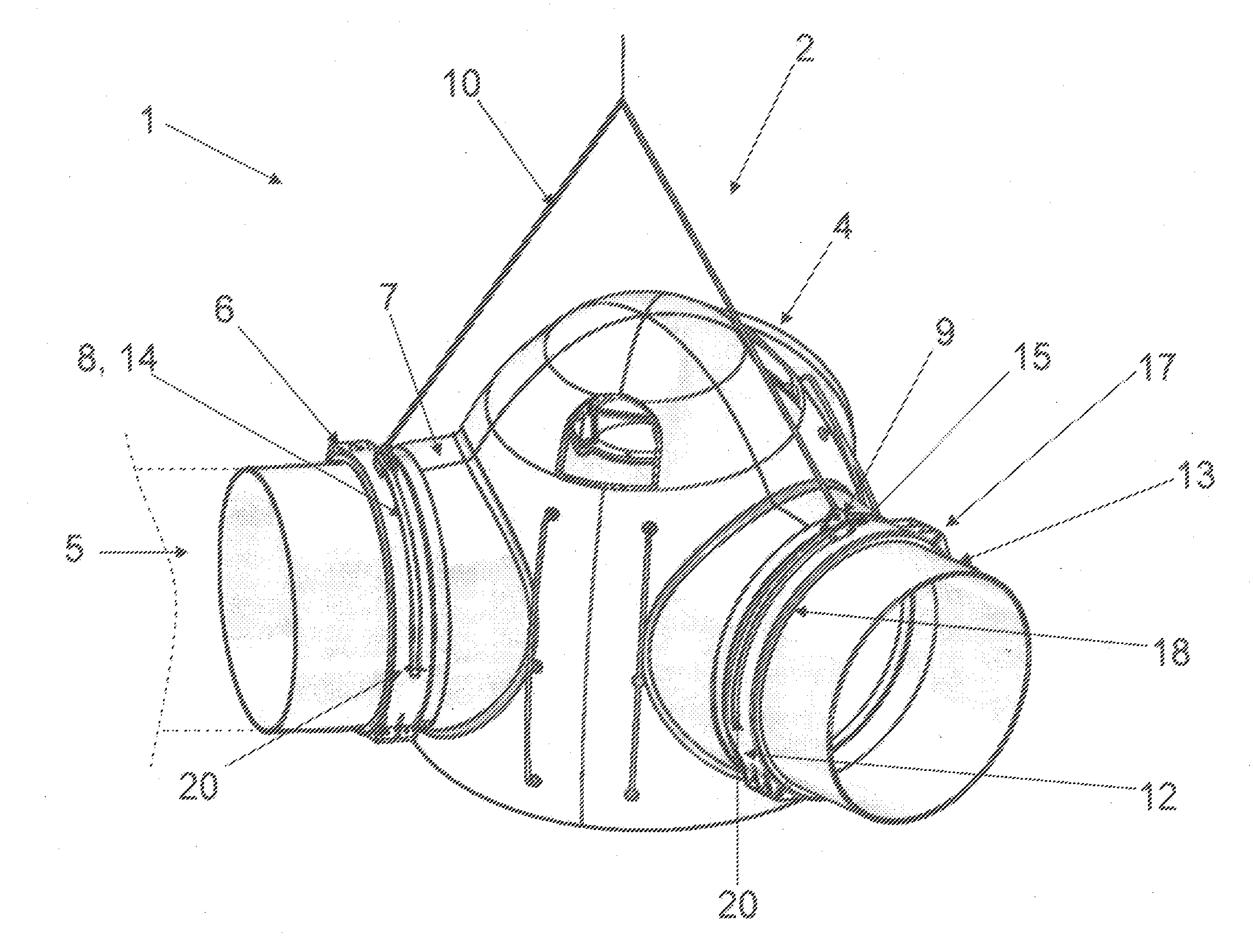
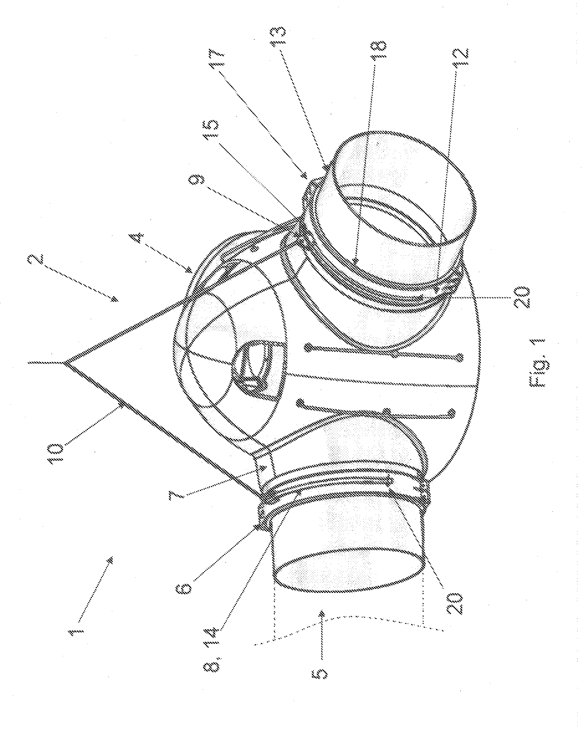
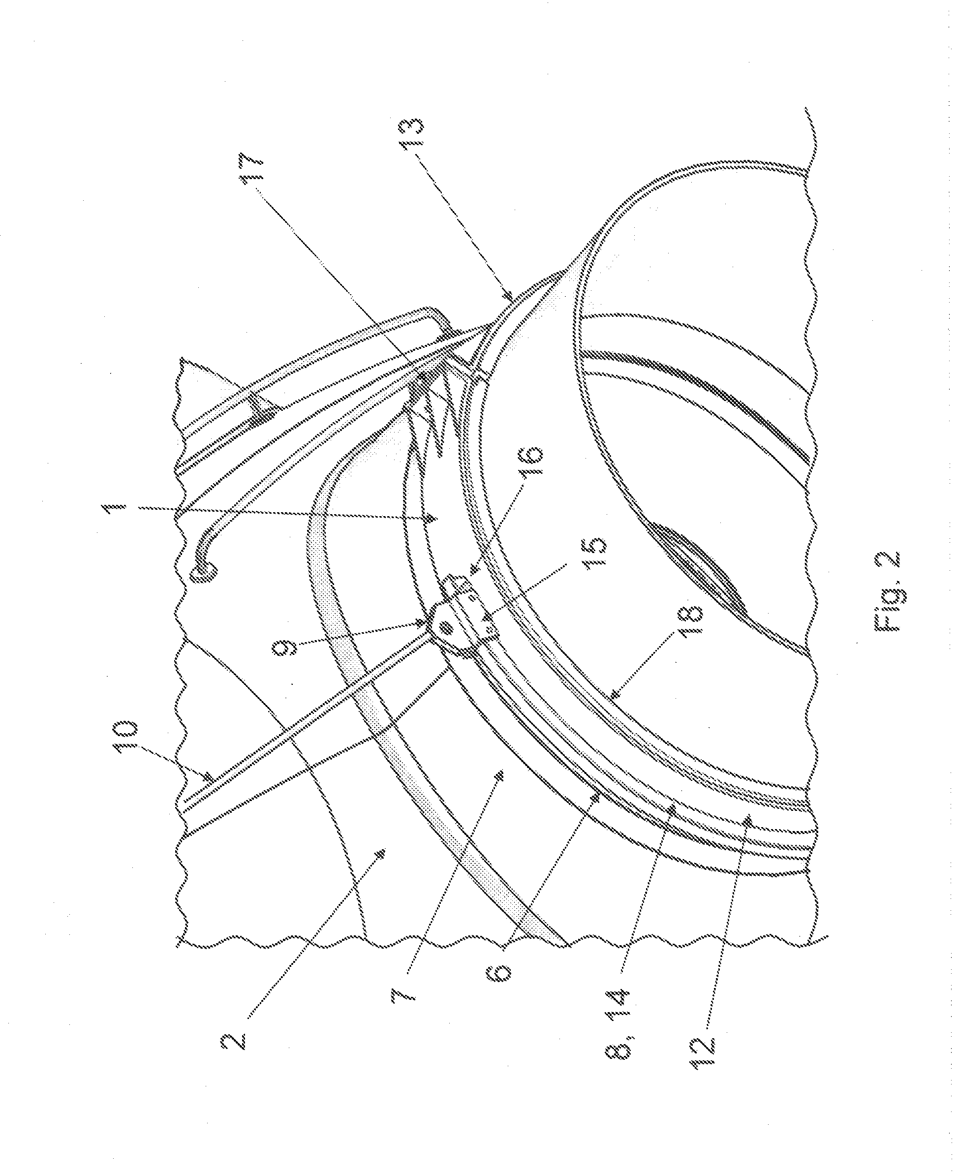
[0019]FIG. 1 shows a first embodiment of a lifting device for a rotor 2. The rotor 2 mounted in FIG. 1 on the lifting device 1 is an integral part of a wind turbine 3 (not shown here) and consists of a turbine hub 4 and in FIG. 1 implied rotor blades 5. The rotor 2 is lifted at the installation site with the lifting device 1 so as to be mounted to a flange (not shown here) of a rotor shaft of a turbine housing. The lifting device 1 comprises receiving devices 6, which are fixed to a respective blade root region 7 of the rotor 2. The receiving devices 6 are composed of two half-shells 12 and 13, which are held together by a connecting element 17. At least one half-shell 12 or 13 of each receiving device 6 has a guiding means 8 mounted thereon, which comprises a carrier element 9 for receiving and fixing cable carriers 10. The carrier element 9 is connected to the guiding means 8 in a movement-flexible manner so that the rotor 2 is aligned properly for assembly before assembling on a ...


PUM


Abstract

The invention relates to a lifting device for a rotor of a wind turbine, consisting of a turbine hub and rotor blades fixed thereon, having the following components: at least one receiving device which can be fixed to a blade root region of the rotor; guiding means which can be attached to the receiving device and which has at least one carrier element for receiving and fixing cable carriers, wherein the carrier element is connected to the guiding means in a movement-flexible manner such that the rotor is aligned properly for assembly before being assembled on a rotor shaft of the wind turbine. The aim of the invention is to provide a lifting device for rotors which is easy to assemble and disassemble and which enables the rotor to automatically align into a correspondingly optimal bearing position for assembling onto the turbine hub when undesired torque acts on said rotor.

Description

TECHNICAL FIELDS[0001]The present invention relates to a lifting device for a rotor of a wind turbine. Such a rotor consists substantially of a turbine hub and rotor blades fixed thereon. The lifting device here has at least one receiving device which can be fixed to a blade root region of the rotor.PRIOR ART[0002]Such a lifting device is known from the prior art. In general, wind turbines and their components have extreme dimensions that make it become necessary from economic aspects to assemble the individual components only at the installation sites. The installation of a rotor of a wind turbine to a flange on the rotor shaft in the turbine casing is here usually accomplished with a crane. This crane is equipped with pulleys which can lift the rotor to the appropriate height. In the simplest case, the pulleys have loops, which are placed around a rotor blade region to hold the rotor before lifting. However, problems often occur in this type of pulleys, which make a lifting of the...

Claims


Application Information

Patent Timeline
IPC IPC(8): F03D11/04
CPCB66C1/108B66C1/62F03D1/001Y02E10/728F05B2230/61F05B2240/916F03D11/04F03D13/10F03D13/20Y02E10/72Y02P70/50F03D13/40
Inventor WAGNER, JUERGEN
Owner SUZLON ENERGY GMBH (DE)
Why Eureka
Try Eureka