Geo-Fence Entry and Exit Notification System

a technology of entry and exit notification and geo-fence, applied in the field of mobile communications devices, can solve the problems of weak gps signals, inaccurate methods, and limited applicability of geo-fence techniques

Active Publication Date: 2013-02-21
PHUNWARE
View PDF7 Cites 306 Cited by
  • Summary
  • Abstract
  • Description
  • Claims
  • Application Information

AI Technical Summary

Problems solved by technology

Unfortunately, this method often yields inaccurate results, since the density of cell towers is often insufficiently large to provide meter-level resolution of the location of a device.
Unfortunately, the applicability of this technique is limited, since the set of known Wi-Fi hot spots is relatively small.
Unfortunately, GPS signals are weak, and it is typically battery intensive for a mobile communications device to receive and process GPS location updates on an ongoing basis.
Regardless of the methodology used to determine the location of a mobile communications device at a given point in time, the problem exists of how to detect when the device has entered or exited a geo-fence.
The technique of periodically reporting the current location of a mobile communications device to a server is problematic for several reasons.
First of all, it raises privacy concerns, because the technique effectively builds a trail of the location of the device over time.
Moreover, periodic reporting is also inefficient since, in order for the server to react to the event of a device crossing a geo-fence in a timely manner, the device must have a high location reporting rate.
However, a high reporting rate consumes energy for both the detection and the submission steps of the process.
In addition, periodic reporting suffers from accuracy issues.
In particular, since the energy profile of GPS is poor, periodic reporting schemes such as those employed in GOOGLE LATITUDE® do not use GPS for location detection.
Consequently, the accuracy of the detected locations is reduced.

Method used


Image

  • Geo-Fence Entry and Exit Notification System
  • Geo-Fence Entry and Exit Notification System
  • Geo-Fence Entry and Exit Notification System

Examples


Embodiment Construction

[0017]It will be appreciated from the foregoing that there is a need in the art for a means for detecting when a mobile communications device crosses a geo-fence. There is further a need in the art for such a means that is private, efficient, accurate, and not battery intensive when implemented on a mobile communications device. These and other needs may be addressed by the systems and methodologies disclosed herein.

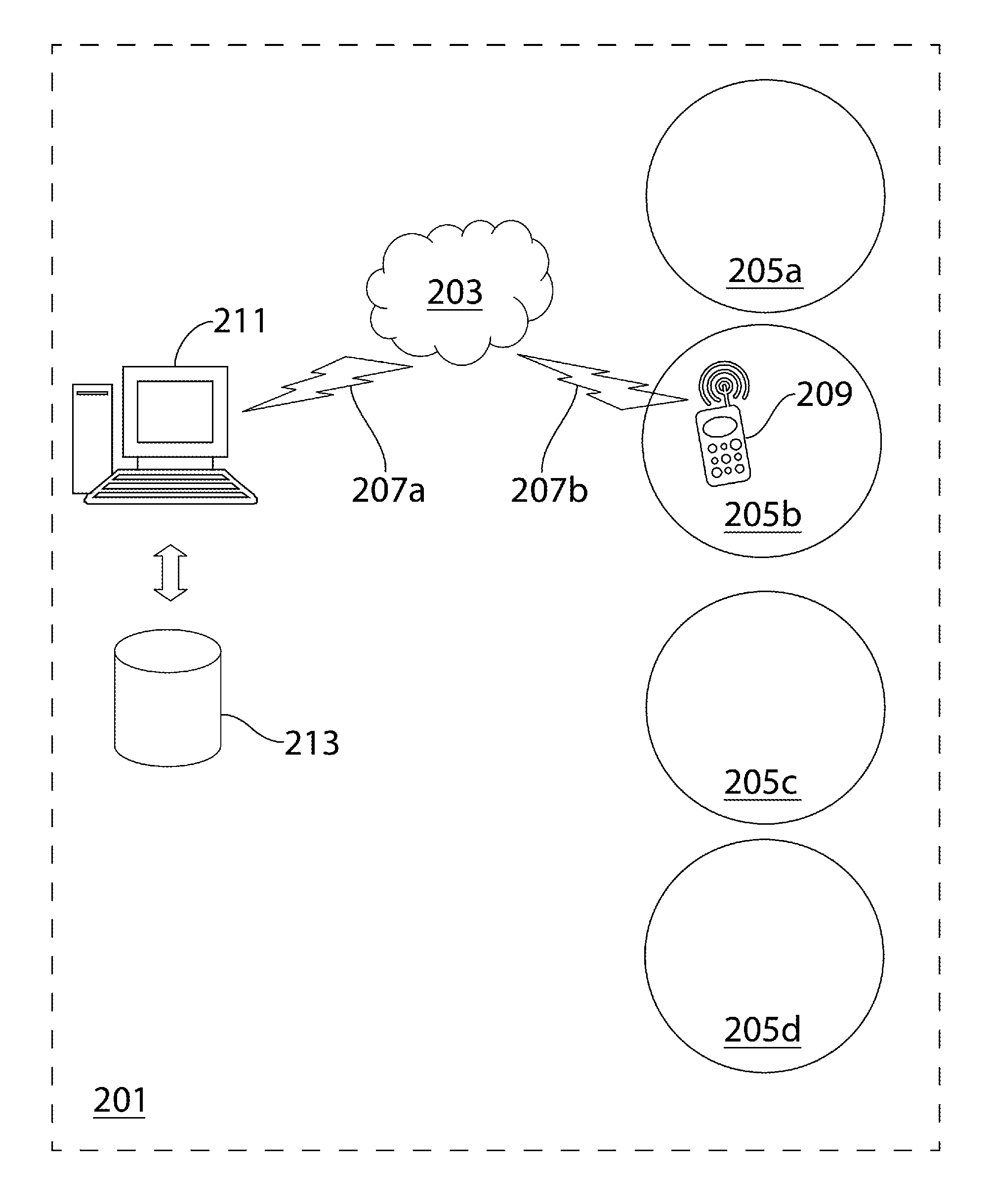
[0018]FIG. 1 illustrates one particular, non-limiting embodiment of a system which may be utilized to implement the methodologies described herein. As seen therein, the system 201 preferably comprises a network 203 equipped with a set of geo-fences 205. The geo-fences 205 consist of a set of areas 205a-d which are defined by geographic boundaries. Such boundaries may be defined, for example, in terms of latitude, longitude, and radius. Irregular areas may be supported in the systems and methodologies described herein as well.

[0019]Suitable network connections 207 are pro...


PUM


Abstract

A method is provided for determining when a mobile communications device has crossed a geo-fence. The method comprises (a) providing a mobile communications device (209) equipped with an operating system and having a location detection application resident thereon, wherein the mobile communications device is in communication with a server (211) over a network (203), and wherein the server maintains a geo-fence database (213); (b) receiving, from the operating system, a notification that (i) the location of the mobile communications device has changed by an amount that exceeds a predetermined threshold, or (ii) that a period of time has passed; (c) querying the operating system for a data set comprising the general location of the mobile communications device and the corresponding location accuracy; (d) transmitting the data set to the server; and (e) receiving from the server, in response to the transmission of the data set, a set of geo-fences (205) proximal to the general location.

Description

CROSS REFERENCE TO RELATED APPLICATIONS[0001]This application claims the benefit of U.S. Provisional Application No. 61 / 525,565, filed Aug. 19, 2011, having the same title, and having the same inventors, and which is incorporated herein by reference in its entirety.FIELD OF THE DISCLOSURE[0002]The present disclosure relates generally to mobile communications devices, and more particularly to methods and systems for determining when a mobile communications device has entered and exited a geo-fence.BACKGROUND OF THE DISCLOSURE[0003]Mobile communications device platforms such as the Apple iPhone and the Google Android have several features that make them useful as location detection devices. Location detection is important in mobile applications that require knowledge of whether a user is entering or exiting defined geographic areas known as geo-fences. For example, in location-based marketing, it is desirable for merchants to know when the user of a mobile device is in the proximity (...

Claims


Application Information

Patent Timeline
Patent Type & Authority Applications(United States)
IPC IPC(8): H04W24/00H04W4/021
CPCG08B21/0277G08B21/0283H04W4/021G01S5/0263G08B21/0288
Inventor OBERMEYER, LANCEOLIVER, ANDREWMILLER, KYLESHETTY, PRASHANTRUSTGI, ADITYA
Owner PHUNWARE
Why Eureka
Try Eureka