
Split Line and Low Voltage Wire Conduit and Transformer Box

a transformer box and low voltage wire technology, applied in the field of electric wiring and conduits, can solve problems such as failure to disclose a unitary condui

Active Publication Date: 2013-02-28
ONEIL RYAN
View PDF11 Cites 14 Cited by
  • Summary
  • Abstract
  • Description
  • Claims
  • Application Information

AI Technical Summary

Benefits of technology

The present invention is a new type of electrical conduit and meter socket box. It solves the problems of previous versions, providing convenience for users when installing and connecting low voltage wires. The items it features include a single conduit for routing multiple types of wiring, markers to identify specific wires, and a split construction that prevents high / low or line / low voltage wires from touching or interfering with each other. Other improvements include a seamless connection to the meter socket box and a ready means of separating high and low voltage wires.

Problems solved by technology

The prior art fails to disclose a unitary conduit having a split pathway therein, along with a split meter box that separates line and low voltage electrical assemblies.

Method used


Image

  • Split Line and Low Voltage Wire Conduit and Transformer Box
  • Split Line and Low Voltage Wire Conduit and Transformer Box
  • Split Line and Low Voltage Wire Conduit and Transformer Box

Examples


Embodiment Construction

[0023]Reference is made herein to the attached drawings. Like reference numerals are used throughout the drawings to depict like or similar elements of the electrical conduit device. For the purposes of presenting a brief and clear description of the present invention, the preferred embodiment will be discussed as used for separating line and low voltage wires in an electrical assembly and when routing such wires within a residence. The figures are intended for representative purposes only and should not be considered to be limiting in any respect.

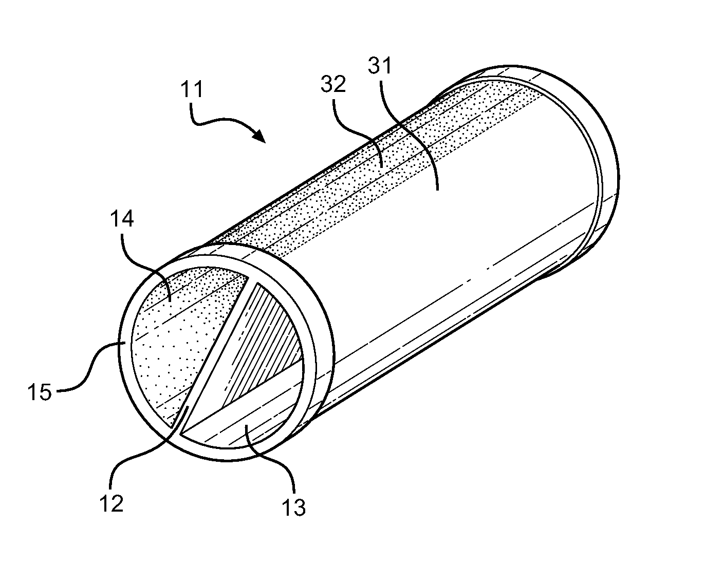
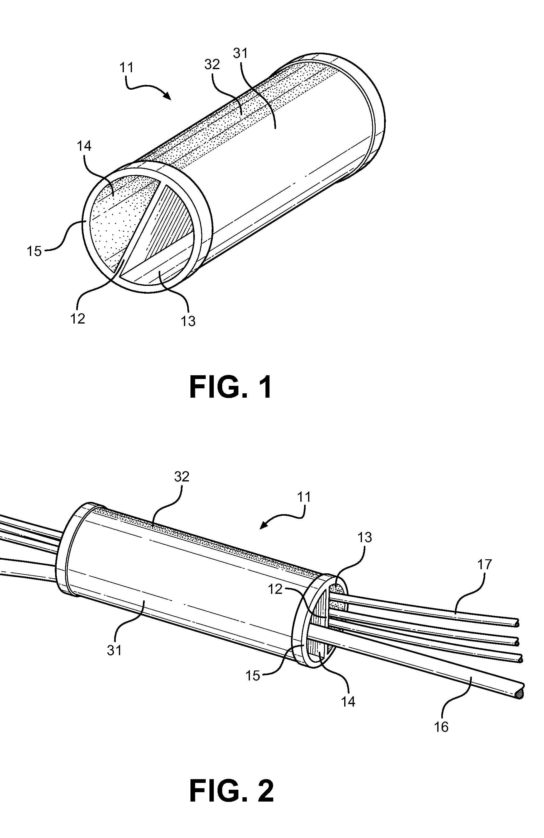
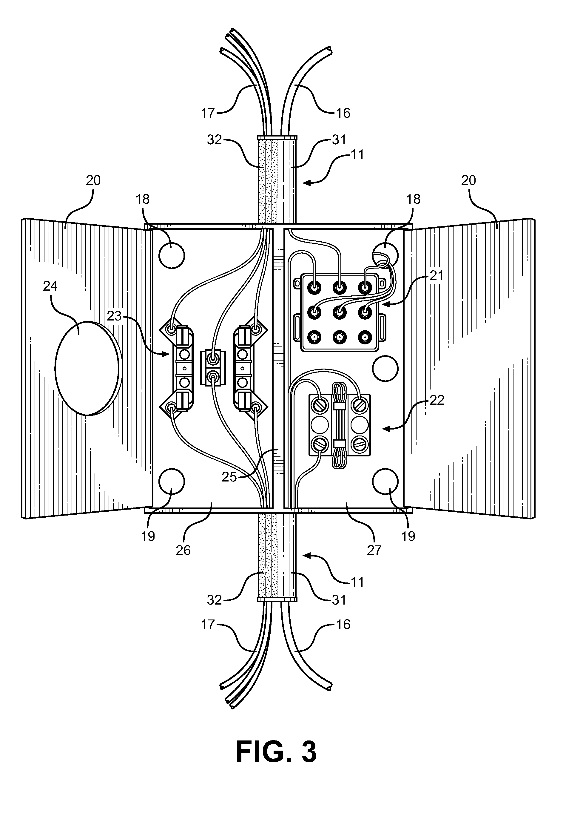
[0024]Referring now to FIG. 1, there is shown a perspective view of the split conduit of the present invention. The conduit 11 comprises an elongated member having an enclosed cross section formed of circular or rounded sidewalls 15 to accept wires and cables therethrough. Within the interior of the cross section is a vertical partition 12 that divides the section into a first 13 and second 14 pathway through the conduit 11. The divided pa...


PUM


Abstract

Disclosed is a split conduit for separating line and low voltage wiring, wherein two wire or cable types are supported and do not interfere with one another along the conduit length. The conduit comprises a rounded outer wall forming an enclosed cross section, wherein a partition is provided within the interior of the conduit that runs along its length to create a first and second pathway. The outer surface of the conduit is discretely marked based on line or low voltage, allowing a user to distinguish what wire type is in each pathway and to locate the partition without inspecting the wires or looking into the interior of the conduit. The split conduit is adapted to be connected to a split meter socket box having a divider for separating connection types, wherein wires from corresponding conduit chambers can be oriented appropriately to establish electrical connectivity within the meter box.

Description

CROSS REFERENCE TO RELATED APPLICATION[0001]This application claims the benefit of U.S. Provisional Application No. 61 / 527,662 filed on Aug. 26, 2011, entitled “O'Neil Conduit.” The above identified patent application is herein incorporated by reference in its entirety to provide continuity of disclosure.BACKGROUND OF THE INVENTION[0002]1. Field of the Invention[0003]The present invention relates to electrical wiring and conduits therefore. More specifically, the present invention relates to a split conduit for low voltage and line voltage, wherein cross talk between wires is eliminated and organization of wires is achieved through the conduit.[0004]Voltage requirements for residential lighting can be broken down into two categories: line voltage and low voltage. Line voltage is the electrical potential that is provided in most residential homes and the voltage utilized without an intermediary transformer on a light fixture. Line voltage is the voltage directly supplied by a power l...

Claims


Application Information

Patent Timeline
Patent Type & Authority Applications(United States)
IPC IPC(8): H05K9/00
CPCH02G3/0481H02G15/117H02G15/115
Inventor O'NEIL, RYAN
Owner ONEIL RYAN
Learn More