Dc-dc converter

a converter and ground electrode technology, applied in the field of dc-dc converters, can solve the problems of switching noise generated by the coil, switching ic leakage from the ground line, and no mounting space is available, so as to achieve the effect of preventing noise current significantly, significantly reducing the leakage of noise current from the ground electrode pattern, and significantly reducing the noise current flowing through the connection electrode pattern

Active Publication Date: 2013-02-28
MURATA MFG CO LTD
View PDF7 Cites 38 Cited by
  • Summary
  • Abstract
  • Description
  • Claims
  • Application Information

AI Technical Summary

Benefits of technology

[0008]Accordingly, preferred embodiments of the present invention provide a DC-DC converter that can significantly reduce and prevent leakage of switching noise, generated by the switching control operation performed by a switching IC, from a ground line via a common ground electrode pattern.
[0010]With this configuration, since the connection electrode that connects the first and second electrode patterns has a small width, the inductance component of the connection pattern is larger than those of the first and second electrode patterns. Further, the first inductor that faces the connection electrode pattern functions as a bead (ferrite bead) and the connection pattern functions as a bead inductor. Hence, the magnetic material of the first inductor absorbs magnetic flux excited by a noise current, and loss is generated by the magnetic resistance of the magnetic material such that the noise current is significantly reduced and prevented. As a result, the noise current input to the ground electrode pattern from the first or second electrode pattern is prevented from leaking from the ground electrode pattern.
[0014]With this configuration, since the connection electrode pattern is sandwiched between the first and second inductors, when a noise current flows through the connection electrode pattern, the two magnetic materials of the first and second inductors absorb the magnetic flux excited by the noise current. As a result, the noise current can be prevented more effectively.
[0015]According to various preferred embodiments of the present invention, a ground electrode pattern is arranged such that a connection electrode pattern facing an inductor has a small width and a first inductor faces the connection electrode pattern such that a noise current flowing through the connection electrode pattern is significantly reduced and prevented. As a result, leakage of the noise current from the ground electrode pattern is significantly reduced and prevented.

Problems solved by technology

In addition, since high-frequency noise (switching noise) is generated during the switching operation performed by a switching IC in a DC-DC converter, it is necessary to take measures against such noise.
Although most of the electromagnetic noise can be removed using a filter formed of, for example, a coil or a capacitor, there is a problem in that no mounting space is available.
Since components are connected to a common ground electrode pattern, switching noise generated by the coil and switching IC leaks from a ground line.

Method used


Image

  • Dc-dc converter
  • Dc-dc converter
  • Dc-dc converter

Examples


first preferred embodiment

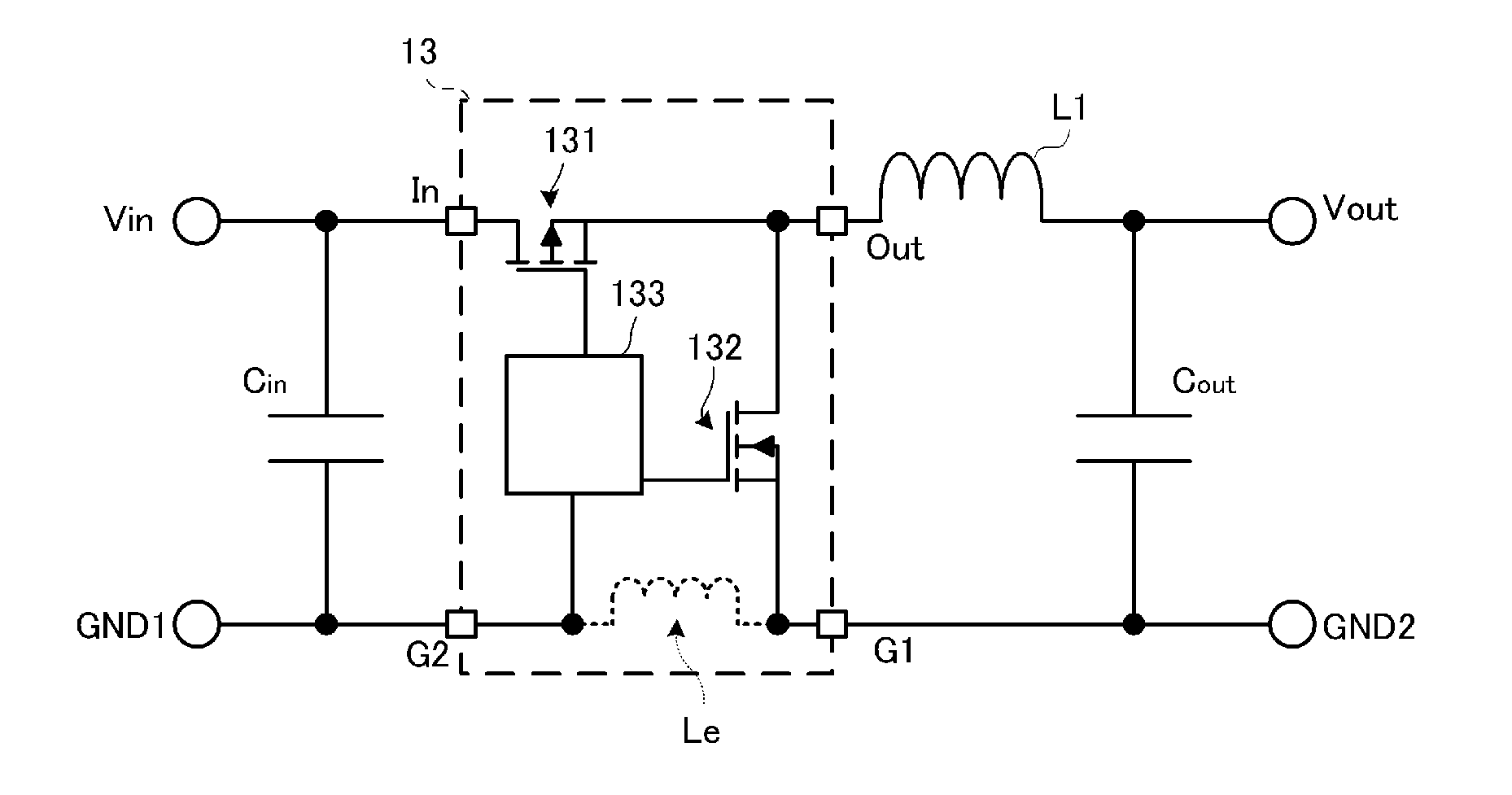
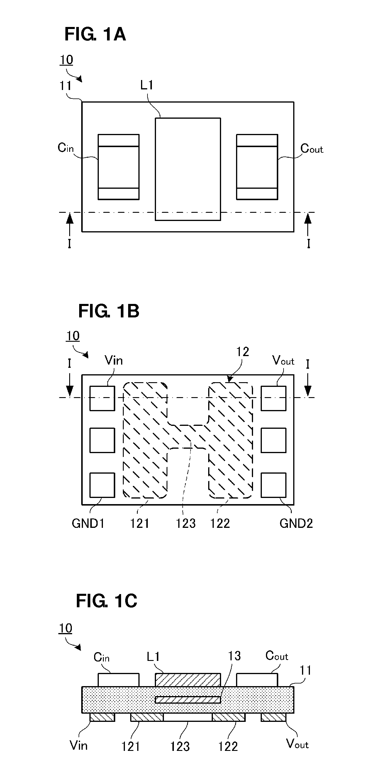
[0024]FIGS. 1A to 1C are schematic diagrams illustrating a configuration of a DC-DC converter 10 according to a first preferred embodiment of the present invention. FIG. 1A is a top view of the DC-DC converter 10. FIG. 1B is a bottom view of the DC-DC converter 10. FIG. 1C is a front cross-sectional view taken along line I-I in FIG. 1A and FIG. 1B.

[0025]The DC-DC converter 10 includes an insulating substrate including a plurality of insulator layers stacked on each other. The insulating substrate 11 has substantially rectangular top and bottom surfaces having long sides. The top surface (first layer) of the insulating substrate 11 is a surface on which a magnetic component and the like are mounted. The bottom surface of the insulating substrate 11 is a surface at which the DC-DC converter 10 is mounted on a circuit board, such as a main board.

[0026]The top surface of the insulating substrate 11 includes an inductor L1 and capacitors Cin and Cout mounted thereon. The inductor L1 is a...

second preferred embodiment

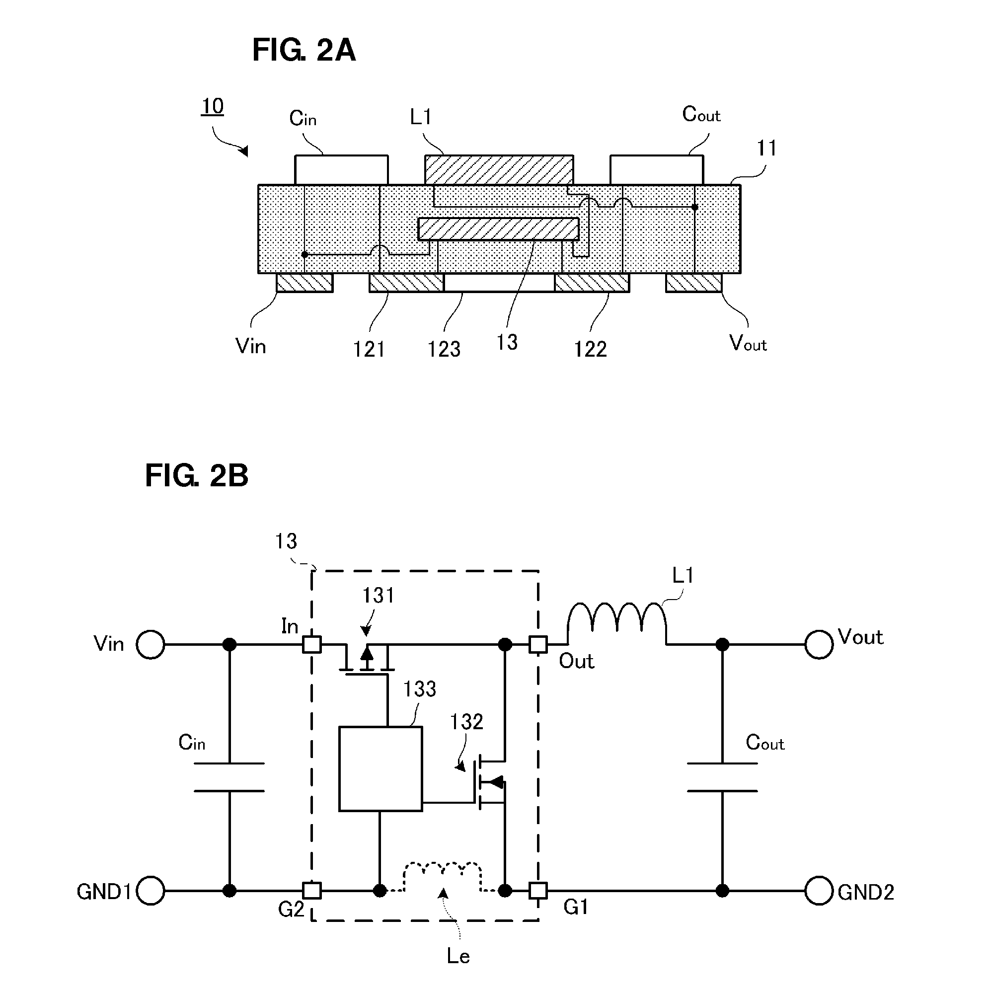
[0043]Hereinafter, a second preferred embodiment according to the present invention will be described. Whereas an example of a step-down DC-DC converter has been described in the first preferred embodiment, an example of a step-up DC-DC converter will be described in the second preferred embodiment, for example. Since the configuration (mounted magnetic components and the like) is preferably the same or substantially the same as that in the first preferred embodiment, the description thereof is omitted.

[0044]FIG. 3A is a schematic diagram illustrating how components are connected in a cross-section of a DC-DC converter 20 according to the second preferred embodiment, and FIG. 3B is an equivalent circuit diagram of the DC-DC converter 20.

[0045]A switching control IC 21 includes the input terminal In, the output terminal Out, and a ground terminal G. The input terminal In is connected to the input terminal electrode Vin through the inductor L1. One end of the capacitor Cin is connecte...

third preferred embodiment

[0058]Hereinafter, a third preferred embodiment according to the present preferred embodiment will be described. A DC-DC converter according to the present preferred embodiment is a multiple-output DC-DC converter, and hereinafter, an example of a two-output DC-DC converter will be described.

[0059]FIGS. 5A to 5C are schematic diagrams illustrating a configuration of a DC-DC converter 30 according to a third preferred embodiment. FIG. 5A is a top view of the DC-DC converter 30 according to the third preferred embodiment, FIG. 5B is a front sectional view taken along line VA-VA in FIG. 5A, and FIG. 5C is a front sectional view taken along line VB-VB in FIG. 5A.

[0060]The DC-DC converter 30 includes an insulating substrate 31. Similarly to the first preferred embodiment, the inductor L1, the capacitor Cin, and a capacitor Cout1 are mounted on the top surface of the insulating substrate 31.

[0061]A switching control IC 32 is provided on an inner layer of the insulating substrate 31. The s...


PUM


Abstract

A DC-DC converter includes an insulating substrate with an inductor provided on the top surface thereof, a switching control IC provided therein, and a ground electrode pattern provided on the bottom surface thereof. The ground electrode pattern includes a first pattern and a second pattern separated from each other and a bridge pattern that connects the first and second patterns to each other. A capacitor and the switching control IC is connected to each of the first and second patterns. The bridge pattern faces the inductor and has a smaller width than that of the first and second patterns.

Description

BACKGROUND OF THE INVENTION[0001]1. Field of the Invention[0002]The present invention relates to DC-DC converters in which an inductor and a switching control IC are provided on an insulator substrate.[0003]2. Description of the Related Art[0004]In cellular phones, multifunctional portable terminals, or the like, a plurality of voltages are required to support multiple frequency bands, and non-isolated DC-DC converters are used. A DC-DC converter includes a coil, capacitors, and a switching IC. An example of an existing DC-DC converter has a configuration in which a coil pattern is formed in an insulator substrate and capacitors and a switching IC are mounted on the surface of the insulator substrate.[0005]In such a configuration, since a DC-DC converter includes a switching IC mounted on the surface of an insulator substrate, the dimension of the DC-DC converter in the thickness direction of the substrate is increased. Accordingly, a smaller (thinner) DC-DC converter is desired in ...

Claims


Application Information

Patent Timeline
Patent Type & Authority Applications(United States)
IPC IPC(8): H02M3/10
CPCH02M3/1588Y02B70/1466H01L23/642H01L23/645H05K1/0253H01L2924/0002H01L25/16H01L2924/00Y02B70/10
Inventor KATO, NOBORU
Owner MURATA MFG CO LTD
Why Eureka
Try Eureka