connector

Active Publication Date: 2013-02-28
JAPAN AVIATION ELECTRONICS IND LTD
View PDF7 Cites 15 Cited by
  • Summary
  • Abstract
  • Description
  • Claims
  • Application Information

AI Technical Summary

Benefits of technology

[0007]It is therefore an object of the present invention to provide a connector which is able to hold an object more securely and eject

Problems solved by technology

However, a large force may be necessary to push the pin to eject the tray if the resilient force is so strong as to h

Method used


Image

  • connector
  • connector
  • connector

Examples


Example

[0032]While the invention is susceptible to various modifications and alternative forms, specific embodiments thereof are shown by way of example in the drawings and will herein be described in detail. It should be understood, however, that the drawings and detailed description thereto are not intended to limit the invention to the particular form disclosed, but on the contrary, the intention is to cover all modifications, equivalents and alternatives falling within the spirit and scope of the present invention as defined by the appended claims.

DESCRIPTION OF PREFERRED EMBODIMENTS

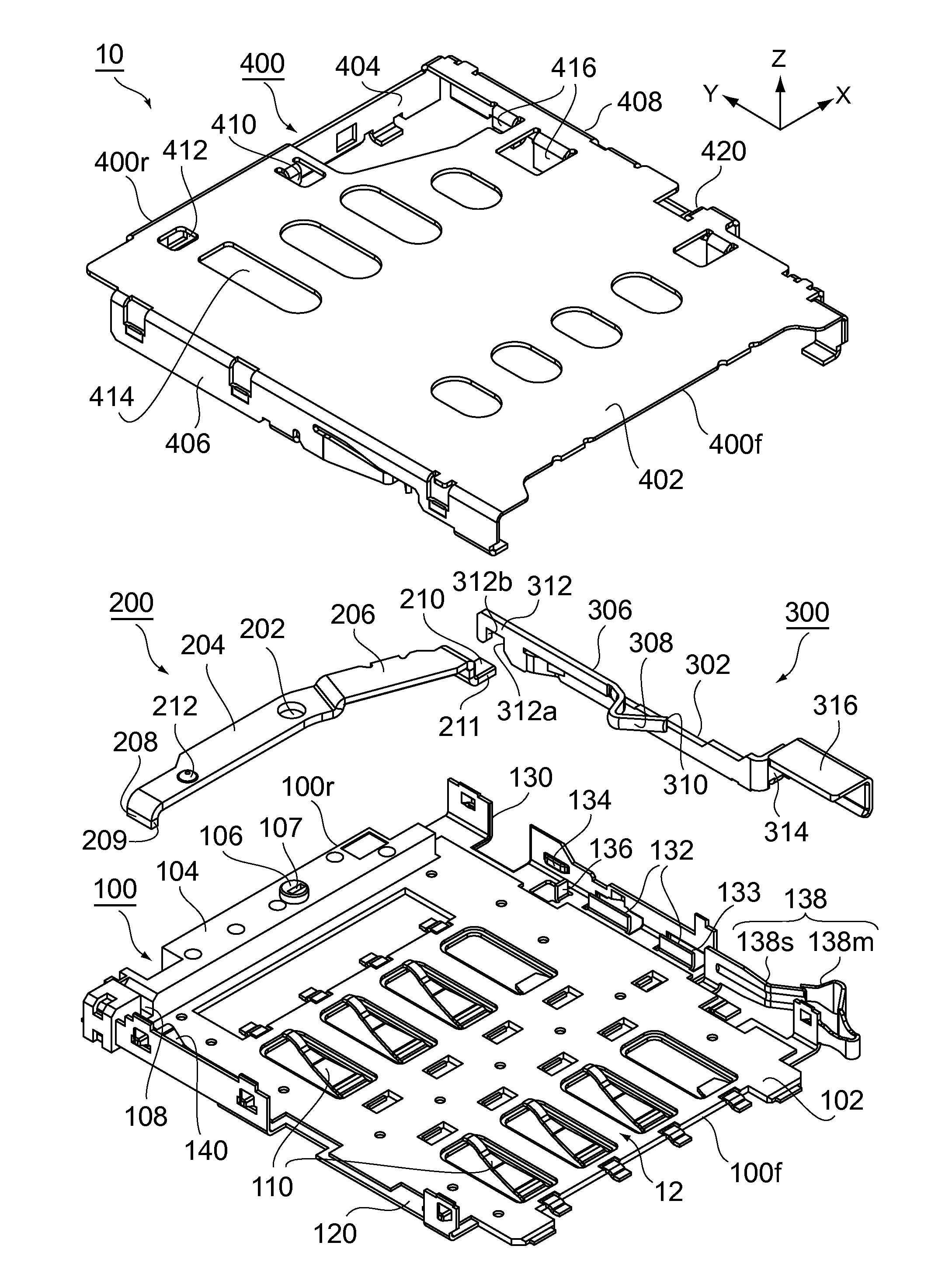
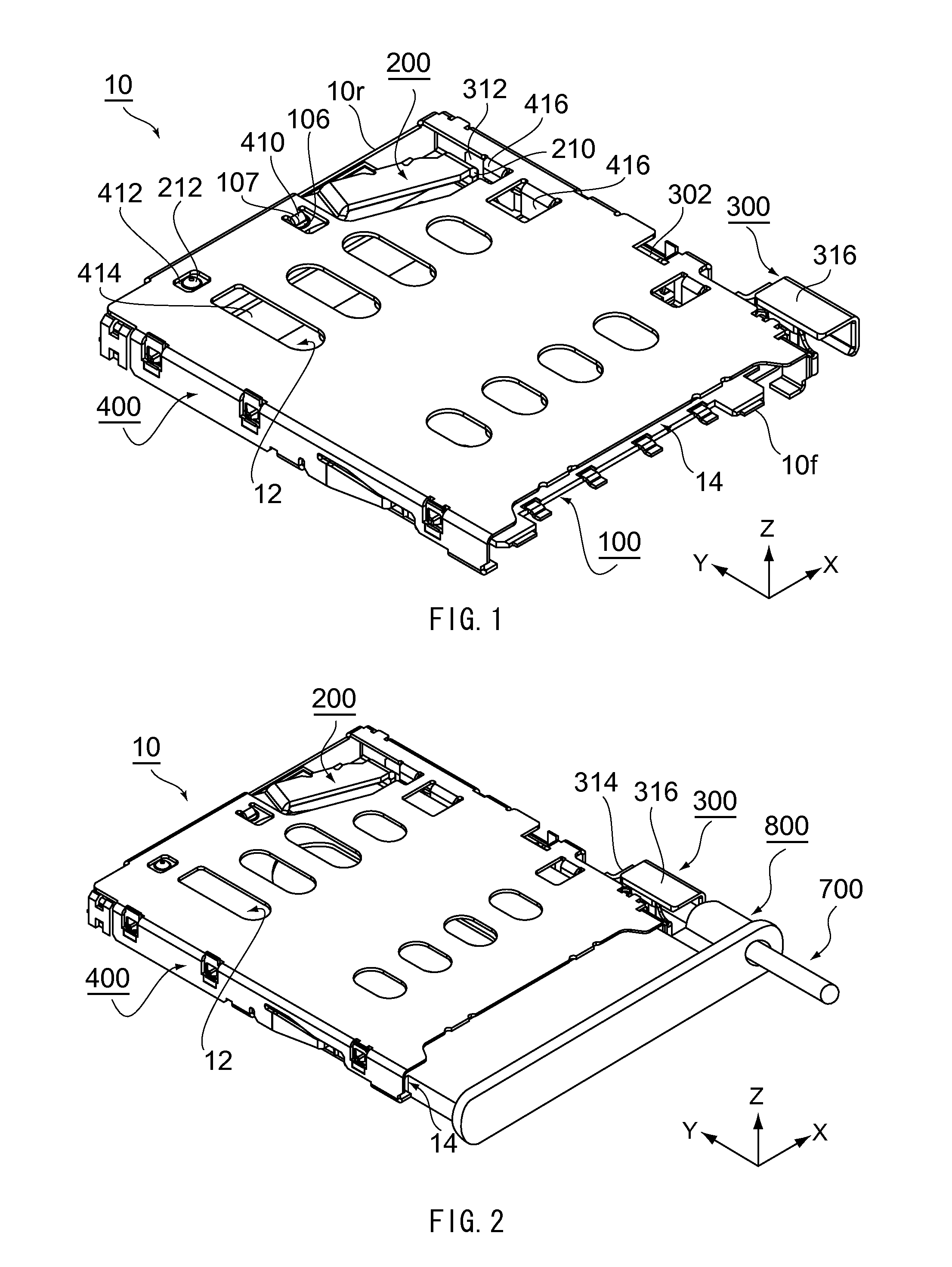
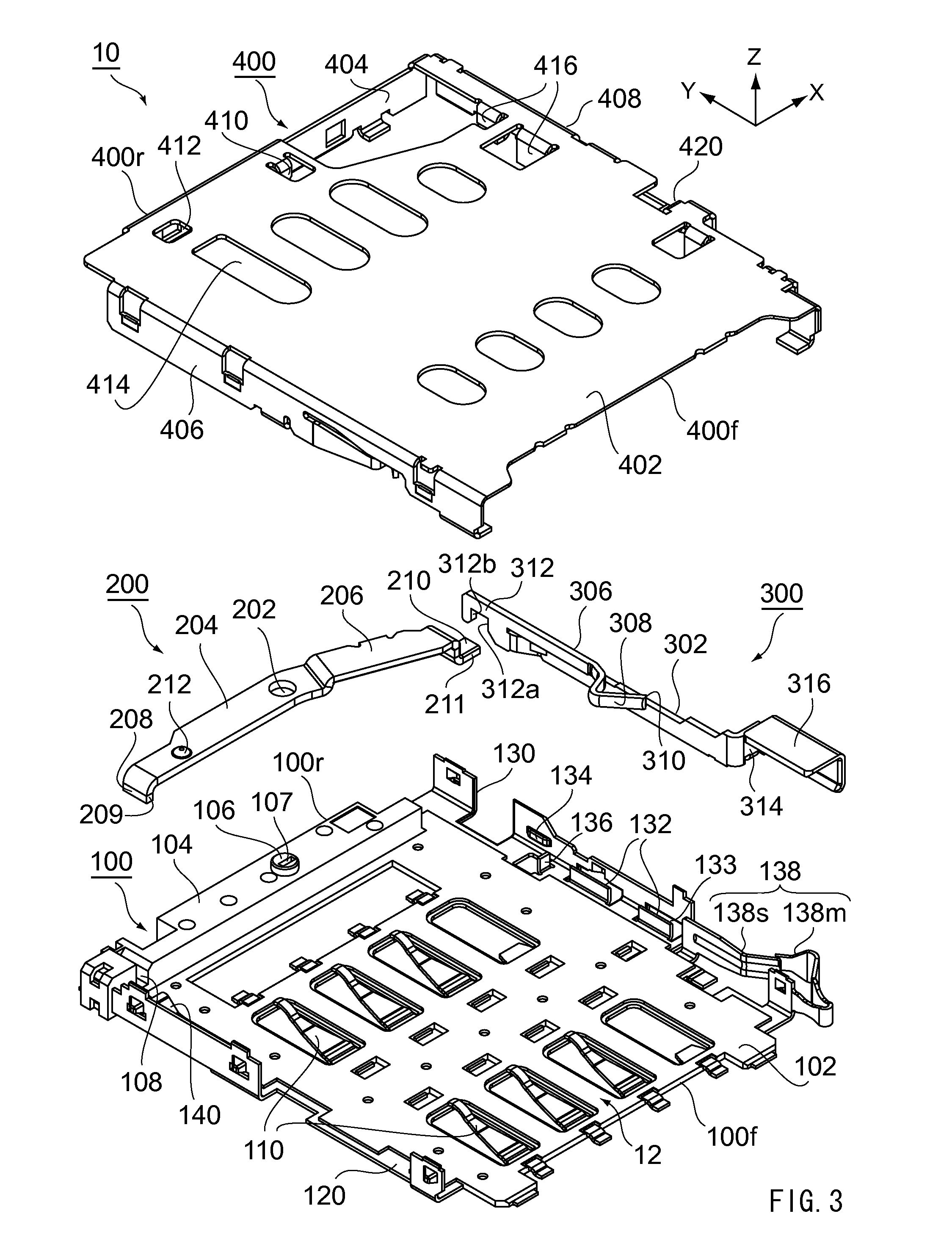
[0033]As shown in FIGS. 1 and 3, the connector 10 according to an embodiment of the present invention is able to be installed, for example, in a cellular phone. The connector 10 comprises a housing 100, an eject lever 200 made of a metal, an eject bar 300 made of a metal and a cover 400 made of a metal. The connector 10 further comprises an accommodating portion 12. The accommodating portion 12 is formed be...


PUM


Abstract

A connector ejects a tray along an eject direction opposite to an insert direction along which the tray is inserted. The connector comprises an eject bar movable along the insert direction, a lock portion movable in a width direction perpendicular to the insert direction, and a stopper. The lock portion moves along the insert direction when the eject bar moves along the insert direction. When the inserted tray is pulled along the eject direction, the tray is brought into abutment with the lock portion. The lock portion in the abutment moves in the width direction to be stopped by the stopper so that the tray is prevented from being ejected. When the eject bar is moved along the insert direction, the lock portion is brought into abutment with the tray. In this case, the lock portion moves in the width direction without being stopped so that the tray is ejected.

Description

CROSS REFERENCE TO RELATED APPLICATIONS[0001]Applicants claim priority under 35 U.S.C. §119 of Japanese Patent Applications No. JP2011-188672 filed Aug. 31, 2011.BACKGROUND OF THE INVENTION[0002]This invention relates to a connector connectable to a card such as a Subscriber Identity Module (SIM) card.[0003]Generally, this type of connector has an eject mechanism in order to eject an object (for example, a card or a tray accommodating a card) from the connector. For example, the aforementioned connector is disclosed in JP-A 2010-129307, US 2009 / 0267677A or US 2008 / 0165508A, contents of which are incorporated herein by reference.[0004]The connector of JP-A 2010-129307 comprises an eject mechanism and a receiving portion (see FIG. 20). The eject mechanism comprises of a moving portion, a cam follower and a coil spring. The moving portion is provided with a heart cam, a lock portion and a received portion. When a card is inserted into the connector, the moving portion, together with th...

Claims


Application Information

Patent Timeline
IPC IPC(8): H05K5/00
CPCG06K13/085G06K13/0825
Inventor KUME, KENTA
Owner JAPAN AVIATION ELECTRONICS IND LTD
Why Eureka
Try Eureka