Load Leveling System of Power System

a power system and load leveling technology, applied in the direction of load forecast in ac network, process and machine control, instruments, etc., can solve the problem that each position cannot work with each other, and achieve the effect of reducing the exchange cost of facilities

Inactive Publication Date: 2013-02-28
HITACHI LTD +1
View PDF5 Cites 5 Cited by
  • Summary
  • Abstract
  • Description
  • Claims
  • Application Information

AI Technical Summary

Benefits of technology

[0014]Also in conditions that a load peak added to a distribution installation increases through the progress of all electricity, a load peak of the distribution in

Problems solved by technology

There is a problem that each position fails to work with each other f

Method used


Image

  • Load Leveling System of Power System
  • Load Leveling System of Power System
  • Load Leveling System of Power System

Examples


first embodiment

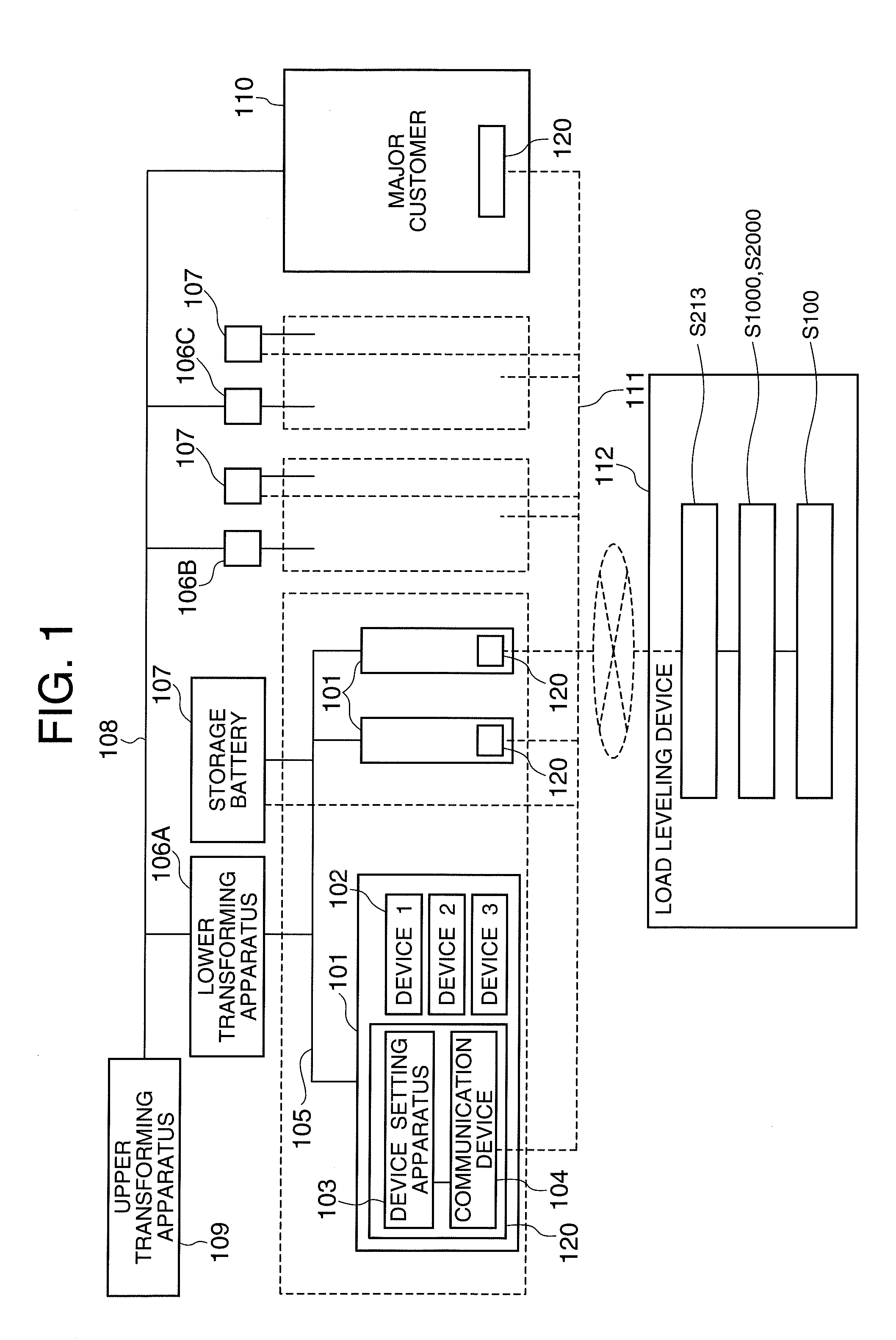
[0031]FIG. 1 is a configuration diagram of a first embodiment of a load leveling system of a power system according to the present invention.

[0032]In this invention, a part of a power system side is described on a premise and this part is specifically constituted as follows. In FIG. 1, a reference numeral 109 denotes, for example, a distribution substation including a distribution transformer, and it supplies power to a customer 101 via a high-voltage transmission line 108, a pole transformer 106, and a low-voltage transmission line 105. The distribution substation further supplies power directly to a major customer 110 from the high-voltage transmission line 108 without the pole transformer 106 and the low-voltage transmission line 105. To the low-voltage transmission line 105, a storage battery 107 may be further connected.

[0033]In this configuration, when the distribution substation 109 including a distribution transformer is supposed to be an upper transforming apparatus, the po...

second embodiment

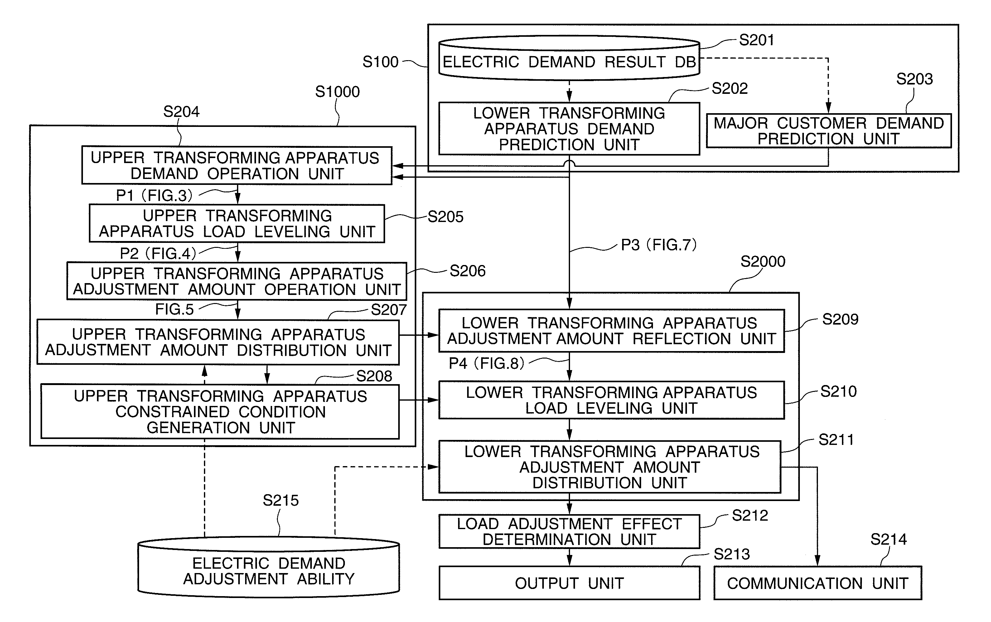
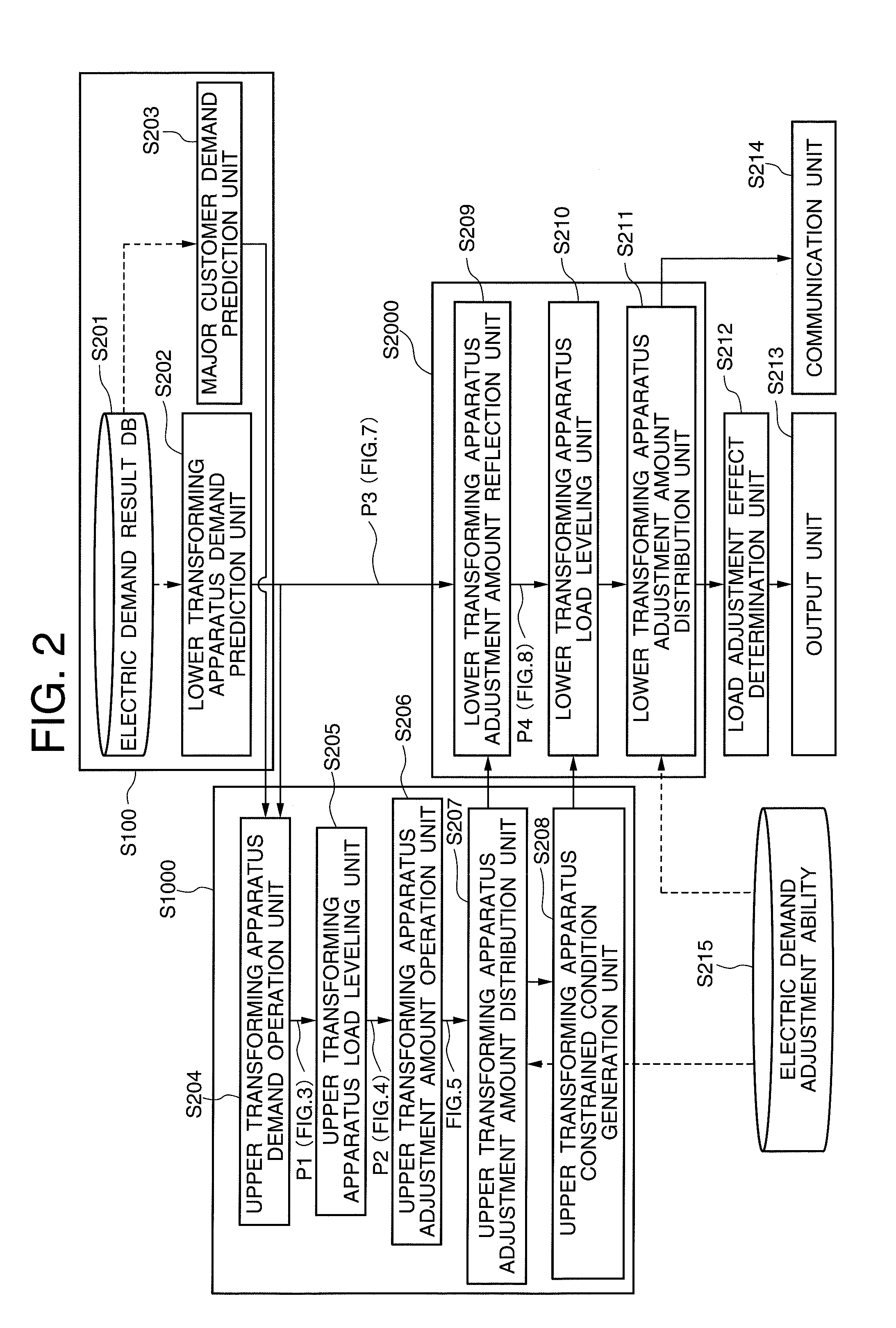
[0043]FIG. 2 is a configuration diagram example illustrating a load leveling system of a power system according to another embodiment of the present invention. In the present embodiment, a configuration of a characteristic portion of the first embodiment will be described in detail. In short, the load leveling device 112 will be further described in detail.

[0044]According to the present embodiment, in FIG. 2 illustrating the second embodiment, “an electric demand prediction unit which divides a future electric demand into an adjustable demand and non-adjustable demand and calculates them for each time zone at least with regard to the lower transforming apparatus and the upper transforming apparatus” corresponds to S100 configured by the electric demand result DB 201 and the demand prediction processing units S202 and S203 which perform the demand prediction of the lower transforming apparatus 106 and the major customer 110.

[0045]In the load leveling device 112 illustrated in a funct...


PUM


Abstract

It is an object of the present invention to provide a load leveling system of a power system capable of attaining load leveling in a distribution substation unit and a method thereof. Disclosed is a load leveling system of a power system with a controller having a major customer and lower transforming apparatus, and with a customer connected to the lower transforming apparatus via a low-voltage line. The system also has a communication unit between the customer and its own system, and control use time zones of devices within the customer; an electric demand prediction unit, and a first load leveling processing unit. By employing such an arranged system, it becomes possible to provide a load leveling system of a power system capable of realizing load leveling of both a distribution substation unit and a pole transformer unit.

Description

INCORPORATION BY REFERENCE[0001]The present application claims priority from Japanese application JP2011-181231 filed on Aug. 23, 2011, the content of which is hereby incorporated by reference into this application.BACKGROUND OF THE INVENTION[0002]The present invention relates to a system for leveling a load of a power system and realizing stabilization of a power system.[0003]In the power system, when all-electric homes further increase by a conventional pace, a power distribution installation (a distribution substation transformer or a pole transformer) needs to be replaced by a large-sized type through an increase in a load. However, there arises a problem that since cost for that purpose is a large burden for an electric power supplier, equipment cost is suppressed.[0004]As one of effective technologies for suppressing a load peak as usual, a demand side management technology is disclosed in JP-A-2007-334523. According to the above technology, in the power system, in the case wh...

Claims


Application Information

Patent Timeline
IPC IPC(8): G06F1/26
CPCH02J3/14H02J2003/003Y04S10/54Y04S20/222Y02B70/3225H02J3/003H02J2310/58H02J3/144
Inventor TAKAHASHI, HIROTAKATOMITA, YASUSHIODA, TAKASHIISOZAKI, ERIONISHI, TSUKASAHORIKOSHI, KAZUHIROMATSUDA, KATSUHIRO
Owner HITACHI LTD
Why Eureka
Try Eureka