
Implant system

An implant system and dental implant technology, applied in the fields of implant, medical science, dentistry, etc., can solve the problem that the angle position between the implant screw fastener and the structural part is not clear, and achieve the effect of reducing the wall thickness

Active Publication Date: 2019-12-24
STRAUMANN HLDG AG +1
View PDF8 Cites 3 Cited by
  • Summary
  • Abstract
  • Description
  • Claims
  • Application Information

AI Technical Summary

Problems solved by technology

However, this solution has the disadvantage that the threaded fastener must be drilled out in order to release the connection between the implant and the abutment, since a reversible release cannot be achieved due to the deformation of the body of the threaded fastener
In this embodiment, however, the relative angular position between the implant threaded fastener and the structural part is not defined

Method used


Image

  • Implant system
  • Implant system
  • Implant system

Examples


Embodiment Construction

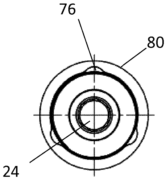
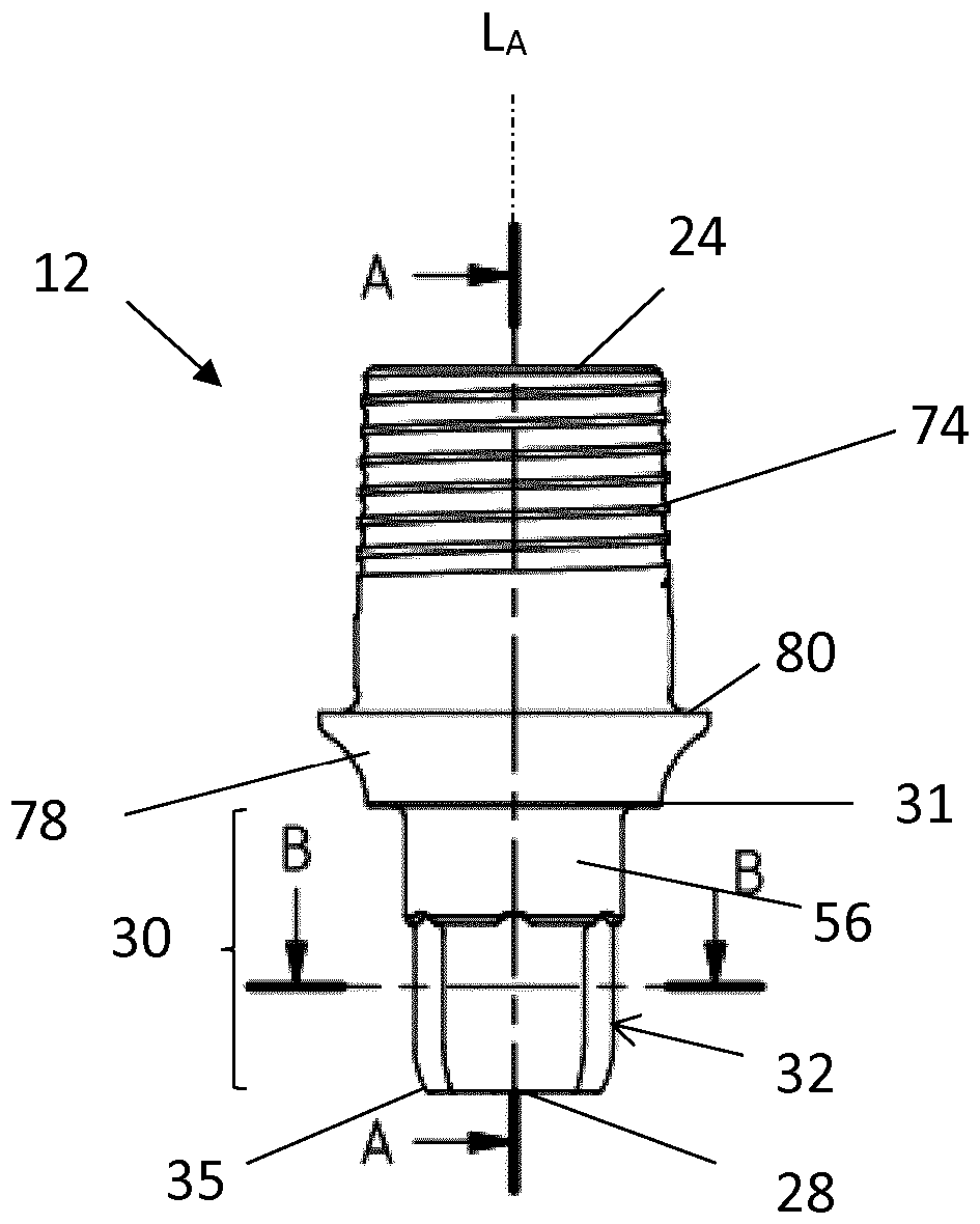
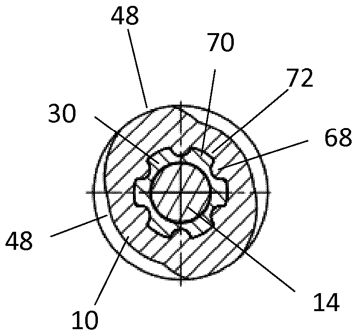
[0062] exist figure 1 An embodiment of the implant system according to the invention is shown in . The implant system comprises a dental implant 10 composed of ceramic material and a structural member 12 connected by means of a threaded fastener 14 (see image 3 ) are stably connected to each other. Preferably, the ceramic components 10 , 12 of the implant system, that is to say the dental implant 10 and the structural part 12 are produced in an injection molding process. Preferably, yttrium-stabilized and / or cerium-stabilized zirconia ceramics are used for their production. Alternatively, other biocompatible materials suitable for ceramics used in the dental field are also conceivable.

[0063] The dental implant 10 is arranged for fixation in the jawbone and along the longitudinal axis L I It extends from the pointed-side end 16 to the coronal-side end 18 . Furthermore, the dental implant has a longitudinal axis L open to the coronal end 18 relative to the dental implan...


PUM


Abstract

The present invention relates to an implant system comprising a dental implant (10) and an abutment (12) which consists of a ceramic material. Said abutment (12) comprises a first anti-rotation element with a plurality of grooves and the dental implant (10) comprises a second anti-rotation element complementary thereto and having a plurality of ribs, the grooves being open towards a proximal end (28) of the abutment (12).

Description

technical field [0001] The invention relates to an implant system (Implantatsystem, sometimes called an implant system) according to the preamble of claim 1 , comprising a dental implant and a structural part (Aufbauteil, sometimes called abutment). Background technique [0002] Two-piece or multi-piece implant systems are best known in the field of dental implantology and typically include an externally threaded dental implant and a structural member (also called a secondary component or "abutment") that defines the Prepared to be fixed in the patient's bone, the structural member serves as the basis for the prosthetic structure. In this case, the structural part usually engages in an opening of the corresponding coronal side of the dental implant, that is to say facing the crown in the implanted state. Combinations consisting of separate dental implants and structural parts are also sometimes referred to in the literature as "two-piece (dental) implants"; in this applicat...

Claims


Application Information

Patent Timeline
Patent Type & Authority Applications(China)
IPC IPC(8): A61C8/00
CPCA61C8/0066A61C8/0068A61C8/0069A61C8/0012A61C8/0022A61C8/0054A61C8/0059A61C13/0006B28B1/24A61L27/10
Inventor J.库尔里克P.森斯福特A.博恩C.帕茨
Owner STRAUMANN HLDG AG
Learn More