Constant-on-time multi-phase switching voltage regulator and related method of generating a regulated voltage

a voltage regulator and constant-on-time technology, applied in the direction of electric variable regulation, instruments, power conversion systems, etc., can solve the problems of nonlinear systems that may respond to drawbacks in prior art systems, and affect the effect of drawbacks

Active Publication Date: 2013-03-07
STMICROELECTRONICS SRL
View PDF1 Cites 14 Cited by
  • Summary
  • Abstract
  • Description
  • Claims
  • Application Information

AI Technical Summary

Benefits of technology

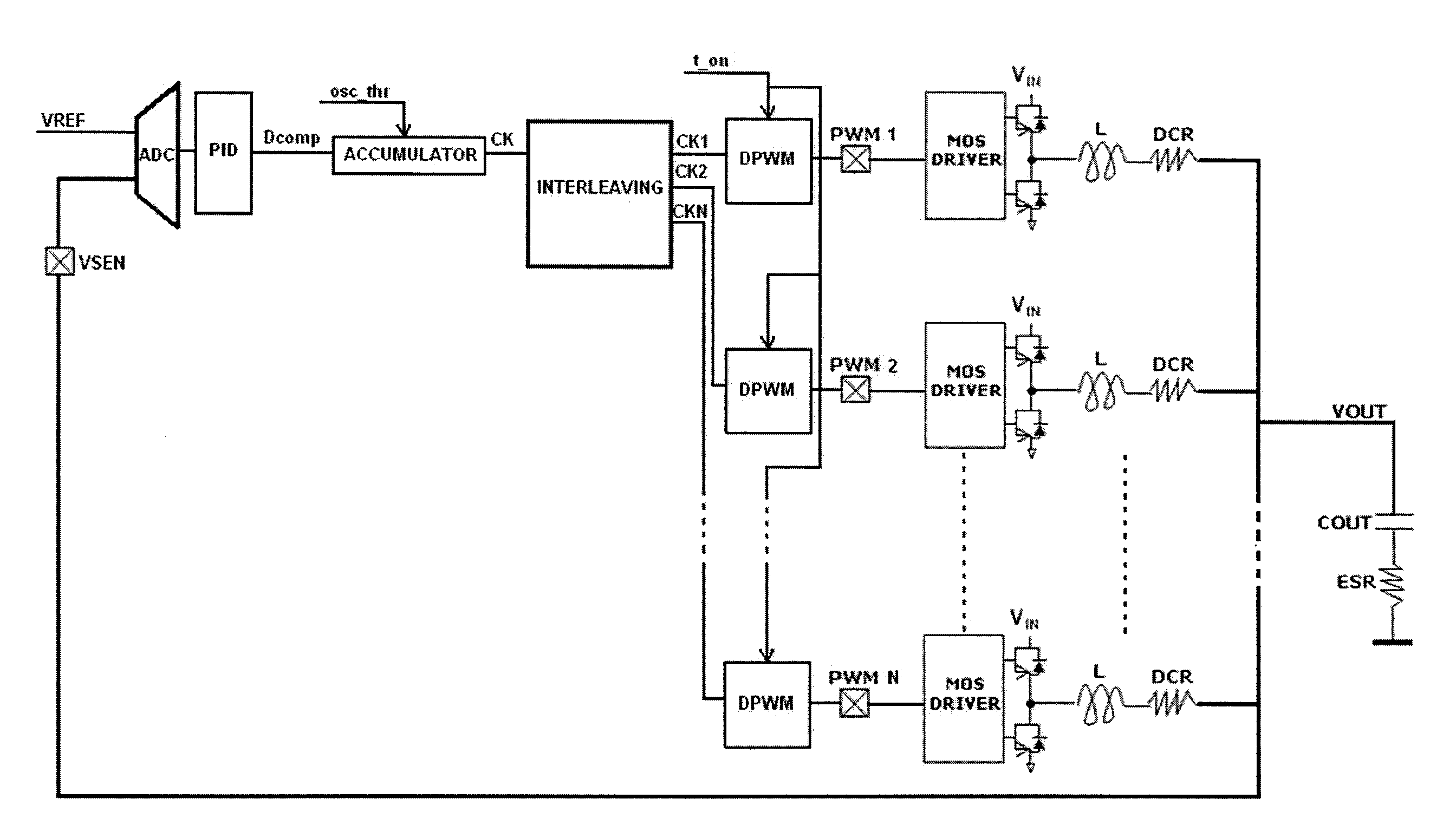
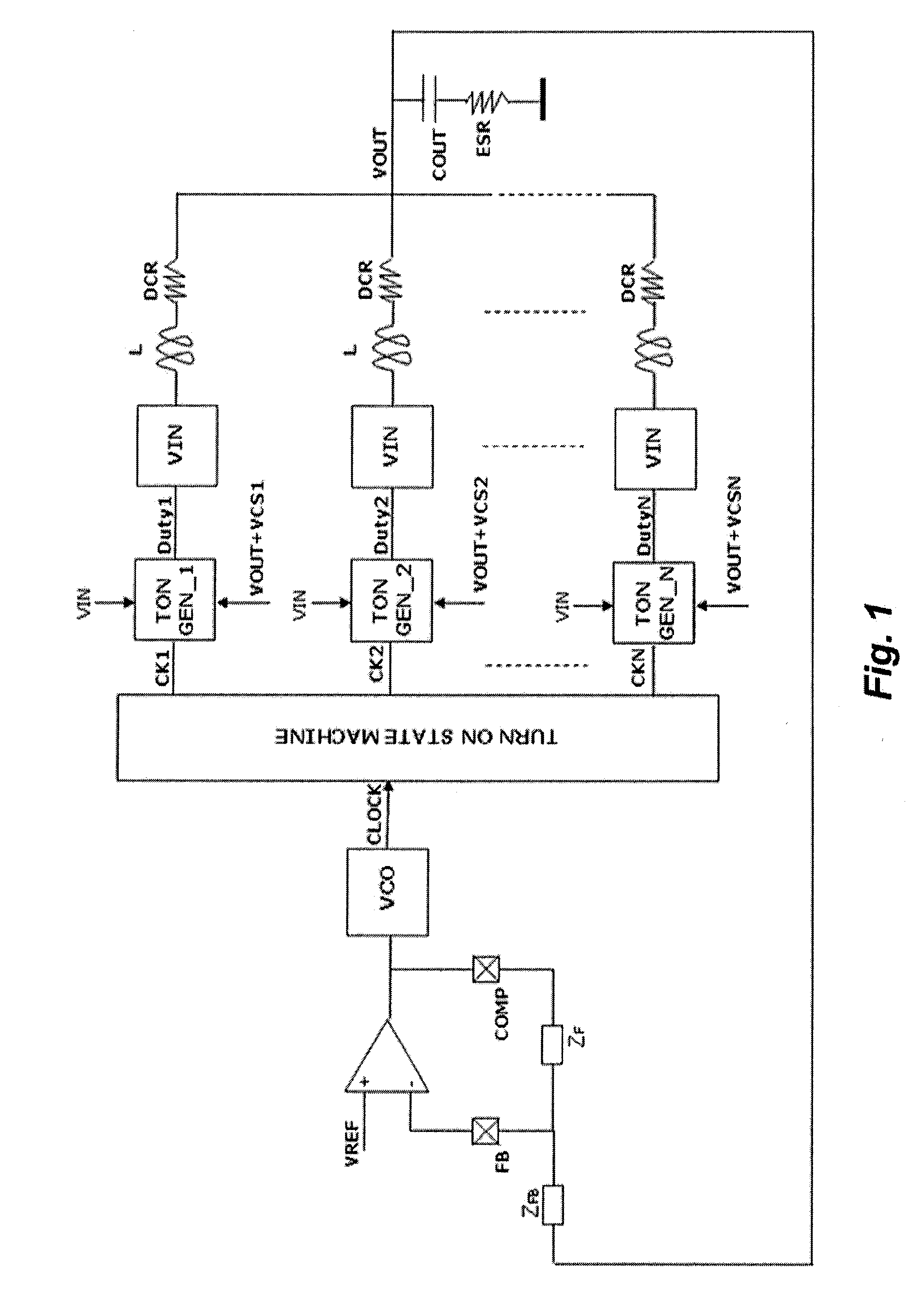
[0010]Prior art nonlinear systems are affected by drawbacks during small load requests. Indeed, they have a fixed triggering threshold and may abruptly turn on all the available phases of the controller. Therefore, such nonlinear systems may not act when the load request is small in respect to the threshold or may act such to make the system respond in an aggressive fashion by turning on all the phases even when it was not necessary. The effect of this nonlinear control is even more evident when the load requests are close to the triggering threshold of the nonlinear system. In these cases, the nonlinear system may respond or even not react at all to small variations giving an undesired response of the load transient. In tests carried out in these conditions, with repeated load transients, large swings of the output voltage exceeding specifications of the regulated voltage were allowed.

Problems solved by technology

Prior art nonlinear systems are affected by drawbacks during small load requests.
Indeed, they have a fixed triggering threshold and may abruptly turn on all the available phases of the controller.
In these cases, the nonlinear system may respond or even not react at all to small variations giving an undesired response of the load transient.

Method used


Image

  • Constant-on-time multi-phase switching voltage regulator and related method of generating a regulated voltage
  • Constant-on-time multi-phase switching voltage regulator and related method of generating a regulated voltage
  • Constant-on-time multi-phase switching voltage regulator and related method of generating a regulated voltage

Examples


Embodiment Construction

[0033]In the following description, numerous specific details are given to provide a thorough understanding of embodiments. The embodiments can be practiced without one or more of the specific details, or with other methods, components, materials, etc. In other instances, well-known structures, materials, or operations, such as, for example, inductors, state machines, error amplifiers, etc., are not shown or described in detail to avoid obscuring aspects of the embodiments.

[0034]Reference throughout this specification to “one embodiment” or “an embodiment” means that a particular feature, structure, or characteristic described in connection with the embodiment is included in at least one embodiment. Thus, the appearances of the phrases “in one embodiment”“according to an embodiment” or “in an embodiment” and similar phrases in various places throughout this specification are not necessarily all referring to the same embodiment. Furthermore, the particular features, structures, or ch...


PUM


Abstract

A switching voltage regulator including a comparison module configured to receive a reference voltage and a feedback voltage and to generate a comparison signal corresponding to a difference between the reference voltage and the feedback voltage, an offset module configured to generate an offset signal based on a number of active phases of the voltage regulator, an adder configured to generate a control signal based on the comparison signal and the offset signal, a plurality of pulse-width-modulated (PWM) power stages, and a control module configured to control the plurality of PWM power stages based at least in part on the control signal generated by the adder.

Description

BACKGROUND[0001]1. Technical Field[0002]This disclosure relates to switching voltage regulators and more particularly to an architecture of constant-on-time multi-phase switching voltage regulator.[0003]2. Description of the Related Art[0004]CPU for PCs, WORKSTATIONS and SERVERS typically need very sophisticated supply control mechanisms. These power supplies must typically meet high precision requirements both in stand-by conditions as well as in conditions of load transients. These requirements led to identify the well known architectures of multi-phase buck regulators as the most appropriate to this objective.[0005]In order to effectively respond to very fast and large load transients (for example, in a CPU, up to 100 A or more in 50 ns) these converters typically employ nonlinear controls that are enabled in presence of load transients and turn on simultaneously all the available phases for sustaining the output voltage. These nonlinear systems advantageously minimize the respon...

Claims


Application Information

Patent Timeline
Patent Type & Authority Applications(United States)
IPC IPC(8): G05F1/10
CPCH02M2001/0012H02M3/1584H02M1/0012
Inventor ZAMBETTI, OSVALDO ENRICOGIORGETTI, DANIELE
Owner STMICROELECTRONICS SRL
Why Eureka
Try Eureka