Electrical Box Safety Redesign

Active Publication Date: 2013-03-07
CASEY DANIEL P
View PDF9 Cites 18 Cited by
  • Summary
  • Abstract
  • Description
  • Claims
  • Application Information

AI Technical Summary

Benefits of technology

The present invention is an electrical control system that can control multiple devices, such as fixtures and appliances, using one main control point. This system also ensures that the main power source is always safely isolated, which prevents electrical shocks and promotes energy conservation. In simple terms, this invention helps to make the household safer and more energy efficient.

Problems solved by technology

Although the benefits of these features cannot be denied, the costs associated with their use can be significant or even burdensome at times. Fossil fuels are a limited natural resource that may be used by municipalities for generating electricity or used directly by the consumer for heating.
Inefficient use of these natural resources creates a higher demand that directly affects a person's finances on a local level while affecting economies of countries on a global scale.

Method used


Image

  • Electrical Box Safety Redesign
  • Electrical Box Safety Redesign
  • Electrical Box Safety Redesign

Examples


Embodiment Construction

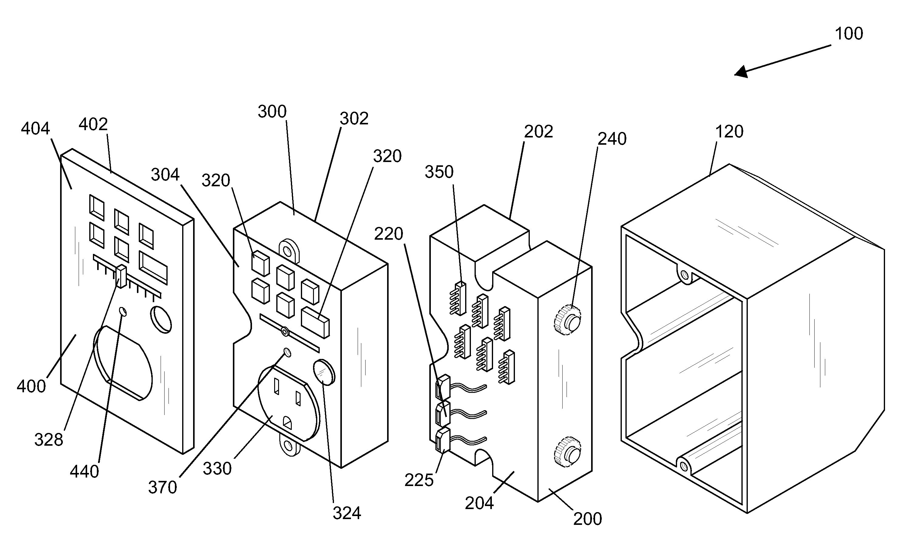
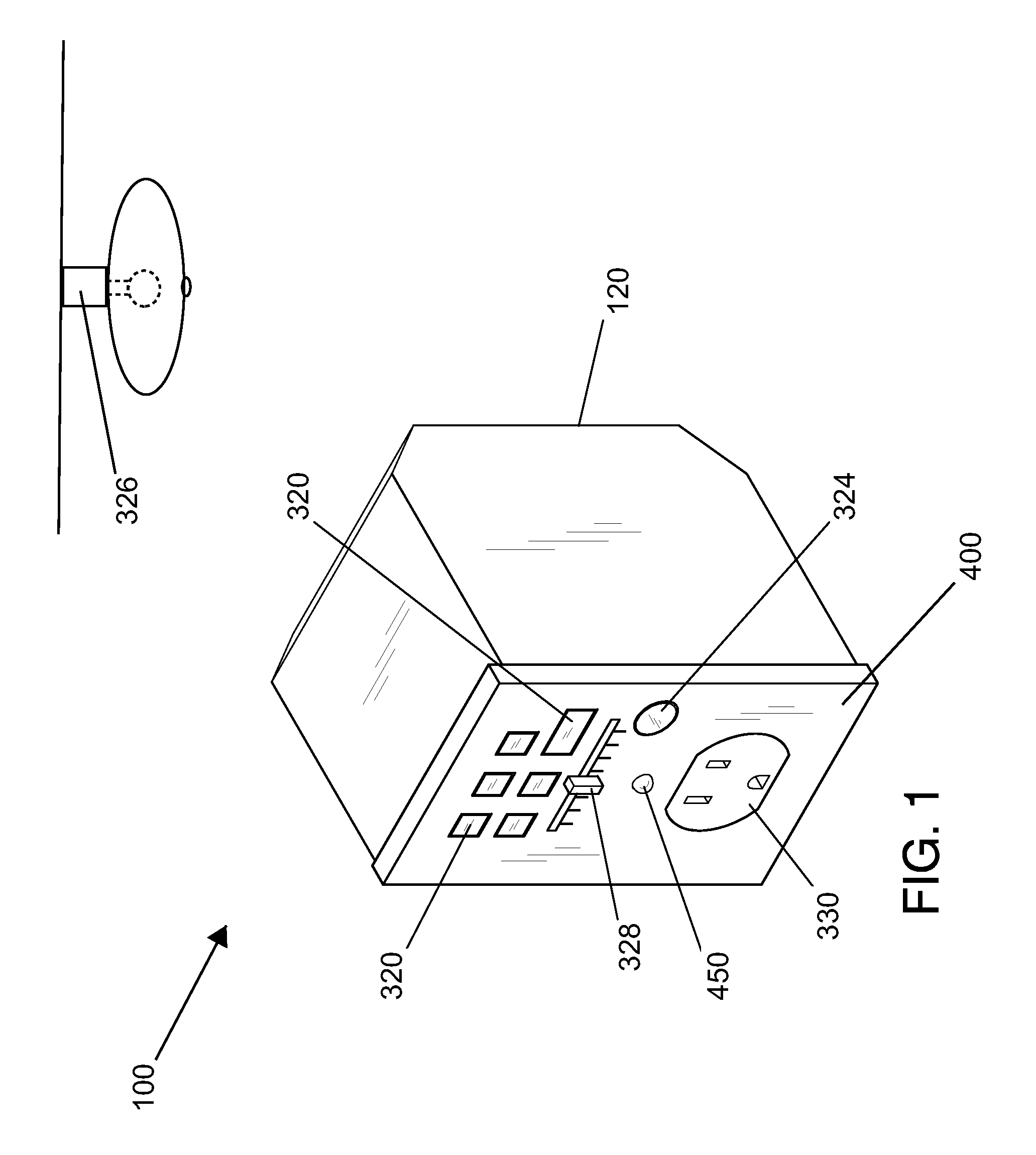
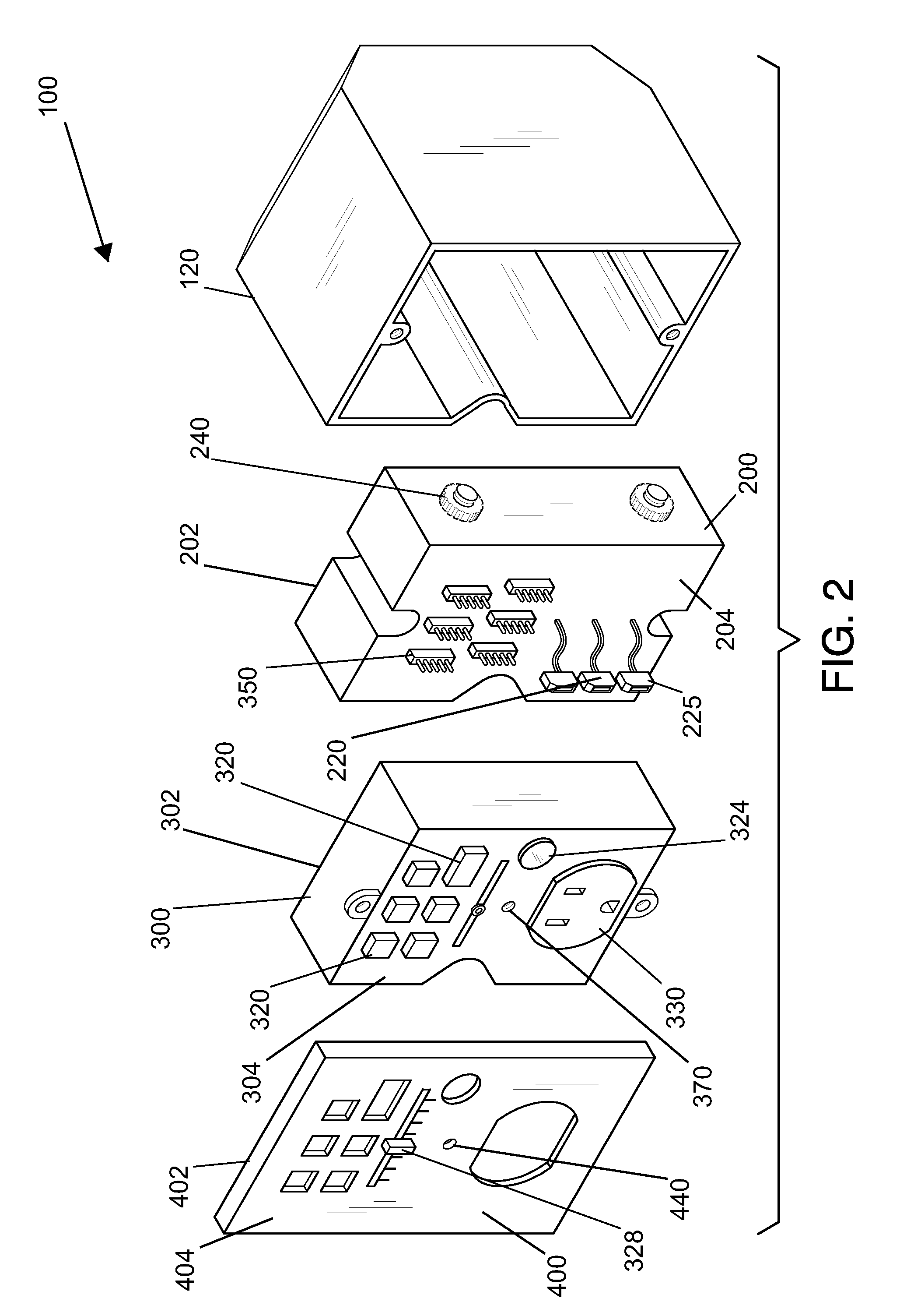
[0014]Following is a list of elements corresponding to a particular element referred to herein:[0015]100 Control system[0016]110 Mounting surface[0017]120 Electrical box[0018]130 Alternating current (AC) power supply[0019]200 Safety block[0020]202 Safety-block rear[0021]204 Safety-block front[0022]206 Safety-block cavity[0023]210 Safety-block alternating current (AC) power supply connector[0024]220 Safety-block alternating current (AC) power transfer connector[0025]225 Safety-block direct current (DC) power transfer connector[0026]240 Leveling screw[0027]250 Safety-block direct current (DC) voltage conversion device[0028]270 Safety-block direct current (DC) battery charger[0029]280 Safety-block direct current (DC) battery pack[0030]300 Control module[0031]302 Control-module rear[0032]304 Control-module user interface[0033]306 Control-module cavity[0034]320 Control-module switch[0035]322 Control-module transmitter[0036]324 Control-module receiver[0037]326 Remote receiver[0038]328 Con...


PUM


Abstract

An electrical control system for fixtures, devices and appliances that safety isolates a power source using the features of the safety block, and consolidates multiple control points to remotely activate a combination of fixtures, devices and appliances using the features of the control module, thereby promoting safety and facilitating energy conservation. The system has a safety block where a safety-block AC power supply connector on the rear attaches to a household alternating current (AC) power supply. The safety-block AC power supply connector passes through a cavity to the safety-block AC power transfer connector located on the front. The system also has a control module with a control-module user interface on the front. A control-module AC power connector connects to the control-module user interface and passes through the control-module cavity to connect to the safety-block AC power transfer connector located on the front of the safety block.

Description

CROSS REFERENCE[0001]This application claims priority to U.S. provisional application Ser. No. 61 / 575,956 filed Sep. 1, 2011, and U.S. provisional application Ser. No. 61 / 262,051 filed Sep. 20, 2011, the specification of which is incorporated herein by reference in its entirety.BACKGROUND OF THE INVENTION[0002]Electricity and other forms of energy have been used in homes and businesses for more than one hundred years to bring illumination and environmental comfort to the occupants. Although the benefits of these features cannot be denied, the costs associated with their use can be significant or even burdensome at times. Fossil fuels are a limited natural resource that may be used by municipalities for generating electricity or used directly by the consumer for heating. Inefficient use of these natural resources creates a higher demand that directly affects a person's finances on a local level while affecting economies of countries on a global scale. The present invention teaches a ...

Claims


Application Information

Patent Timeline
IPC IPC(8): H05K5/00
CPCH05K7/1432H02G3/16
Inventor CASEY, DANIEL P.
Owner CASEY DANIEL P
Why Eureka
Try Eureka