System electrostatic discharge circuit

Active Publication Date: 2019-03-07
NUVOTON
View PDF0 Cites 0 Cited by
  • Summary
  • Abstract
  • Description
  • Claims
  • Application Information

AI Technical Summary

Benefits of technology

[0004]The invention provides a system electrostatic discharge circuit capable of determining whether a transient voltage suppressor diode needs to be replaced by recording a state of

Problems solved by technology

For electronic apparatuses, electrostatic discharge (ESD) may cause permanent damage to semiconductor devices and computer systems and thus affect circuit functions of integrated circuits (ICs).
As a result, electronic products ma

Method used


Image

  • System electrostatic discharge circuit
  • System electrostatic discharge circuit

Examples


first embodiment

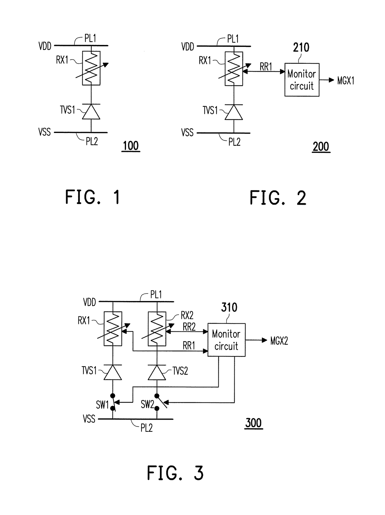
[0016]FIG. 1 is a schematic circuit diagram illustrating a system electrostatic discharge circuit according to the invention. Referring to FIG. 1, a system electrostatic discharge circuit 100 includes a first transient voltage suppressor (TVS) diode TVS1 and a first resistance element RX1. A resistance value of the first resistance element RX1 is proportional to a sum of currents flowing through the first resistance element RX1. In addition, the system electrostatic discharge circuit 100 may be formed on any type of substrate, such as a printed circuit board (PCB), a flexible printed circuit (FPC), or the like. In addition, in the substrate, circuits (i.e., a plurality of electronic devices) having a plurality of different functions and a plurality of wirings (e.g., signal line, power line, or grounding line) for different purposes are disposed on the substrate in addition to the electrostatic discharge circuit 100. In addition, the circuits on the substrate are coupled to each othe...

second embodiment

[0020]FIG. 2 is a schematic circuit diagram illustrating a system electrostatic discharge circuit according to the invention. Referring to FIGS. 1 and 2, in the embodiment, a system electrostatic discharge circuit 200 further includes a monitor circuit 210. In addition, similar or same components are referred to by similar or same reference symbols. The monitor circuit 210 is coupled to the first resistance element RX1 to detect the resistance value RR1 of the first resistance element RX1 and compare a resistance value RR1 of the first resistance element RX1 with the resistance threshold. When the resistance value RR1 of the first resistance element RX1 is greater than or equal to the resistance threshold, the monitor circuit 210 may transmit a warning message MGX1. When the resistance value RR1 of the first resistance element RX1 is less than the resistance threshold, the monitor circuit 210 does not transmit a signal.

[0021]In the embodiment, the warning message MGX1 may be a warni...

third embodiment

[0023]FIG. 3 is a schematic circuit diagram illustrating a system electrostatic discharge circuit according to the invention. Referring to FIGS. 1 and 3, in the embodiment, a system electrostatic discharge circuit 300 may further include a second transient voltage suppressor diode TVS2, a second resistance element RX2, a first switch SW1, a second switch SW2, and a monitor circuit 310. In addition, a second resistance value RR2 of the second resistance element RX2 is proportional to a sum of currents flowing through the second resistance element RX2.

[0024]The first resistance element RX1, the first transient voltage suppressor diode TVS1, and the first switch SW1 are coupled in series between the first power line PL1 and the second power line PL2. The second resistance element RX2, the second transient voltage suppressor diode TVS2, and the second switch SW2 are coupled in series between the first power line PL1 and the second power line PL2. The monitor circuit 310 is coupled to th...


PUM


Abstract

A system electrostatic discharge circuit is provided. The system electrostatic discharge circuit includes a first transient voltage suppressor diode and a first resistance element. The first resistance element and the first transient voltage suppressor diode are coupled in series between a first power line and a second power line. In addition, a resistance value of the first resistance element is proportional to a sum of currents flowing through the first resistance element.

Description

CROSS-REFERENCE TO RELATED APPLICATION[0001]This application claims the priority benefit of Taiwan application no. 106130587, filed on Sep. 7, 2017. The entirety of the above-mentioned patent application is hereby incorporated by reference herein and made a part of this specification.BACKGROUND OF THE INVENTION1. Field of the Invention[0002]The invention relates to an electrostatic discharge (ESD) circuit, and particularly relates to a system electrostatic discharge circuit.2. Description of Related Art[0003]For electronic apparatuses, electrostatic discharge (ESD) may cause permanent damage to semiconductor devices and computer systems and thus affect circuit functions of integrated circuits (ICs). As a result, electronic products may not be able to work normally. Therefore, electrostatic discharge protection circuits are commonly disposed in electronic apparatuses to suppress the influence of electrostatic discharge. However, based on the circuit design and properties of electroni...

Claims


Application Information

Patent Timeline
IPC IPC(8): H02H1/00H02H9/04H02H9/00
CPCH02H1/0007H02H9/04H02H9/005H02H1/0061H01L27/0255H01L27/0288H01L27/0296H02H9/042
Inventor CHANG, PAO-SHU
Owner NUVOTON
Why Eureka
Try Eureka